- 您現(xiàn)在的位置:買賣IC網(wǎng) > PDF目錄10057 > LTC2240IUP-12#TRPBF (Linear Technology)IC ADC 12BIT 170MSPS 64-QFN PDF資料下載
參數(shù)資料
| 型號: | LTC2240IUP-12#TRPBF |
| 廠商: | Linear Technology |
| 文件頁數(shù): | 13/30頁 |
| 文件大?。?/td> | 0K |
| 描述: | IC ADC 12BIT 170MSPS 64-QFN |
| 標準包裝: | 2,000 |
| 位數(shù): | 12 |
| 采樣率(每秒): | 170M |
| 數(shù)據(jù)接口: | 并聯(lián) |
| 轉換器數(shù)目: | 1 |
| 功率耗散(最大): | 638mW |
| 電壓電源: | 單電源 |
| 工作溫度: | -40°C ~ 85°C |
| 安裝類型: | 表面貼裝 |
| 封裝/外殼: | 64-WFQFN 裸露焊盤 |
| 供應商設備封裝: | 64-QFN(9x9) |
| 包裝: | 帶卷 (TR) |
| 輸入數(shù)目和類型: | 1 個差分,雙極 |
第1頁第2頁第3頁第4頁第5頁第6頁第7頁第8頁第9頁第10頁第11頁第12頁當前第13頁第14頁第15頁第16頁第17頁第18頁第19頁第20頁第21頁第22頁第23頁第24頁第25頁第26頁第27頁第28頁第29頁第30頁
LTC2240-12
20
224012fd
APPLICATIONS INFORMATION
DIGITAL OUTPUTS
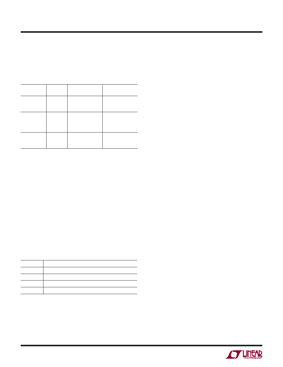
Table 1 shows the relationship between the analog input
voltage, the digital data bits, and the overow bit.
Table 1. Output Codes vs Input Voltage
AIN+ – AIN–
(2V Range)
OF
D11 – D0
(Offset Binary)
D11 – D0
(2’s Complement)
>+1.000000V
+0.999512V
+0.999024V
1
0
1111 1111 1111
1111 1111 1110
0111 1111 1111
0111 1111 1110
+0.000488V
0.000000V
–0.000488V
–0.000976V
0
1000 0000 0001
1000 0000 0000
0111 1111 1111
0111 1111 1110
0000 0000 0001
0000 0000 0000
1111 1111 1111
1111 1111 1110
–0.999512V
–1.000000V
<–1.000000V
0
1
0000 0000 0001
0000 0000 0000
1000 0000 0001
1000 0000 0000
Digital Output Modes
The LTC2240-12 can operate in several digital output
modes: LVDS, CMOS running at full speed, and CMOS
demultiplexed onto two buses, each of which runs at half
speed. In the demultiplexed CMOS modes the two buses
(referred to as bus A and bus B) can either be updated on
alternate clock cycles (interleaved mode) or simultaneously
(simultaneous mode). For details on the clock timing, refer
to the timing diagrams.
The LVDS pin selects which digital output mode the part
uses. This pin has a four-level logic input which should
be connected to GND, 1/3VDD, 2/3VDD or VDD. An external
resistor divider can be used to set the 1/3VDD or 2/3VDD
logic values. Table 2 shows the logic states for the LVDS pin.
Table 2. LVDS Pin Function
LVDS
DIGITAL OUTPUT MODE
GND
Full-Rate CMOS
1/3VDD
Demultiplexed CMOS, Simultaneous Update
2/3VDD
Demultiplexed CMOS, Interleaved Update
VDD
LVDS
Digital Output Buffers (CMOS Modes)
Figure 13a shows an equivalent circuit for a single
output buffer in the CMOS output mode. Each buffer is
powered by OVDD and OGND, which are isolated from the
ADC power and ground. The additional N-channel transistor
in the output driver allows operation down to voltages as
low as 0.5V. The internal resistor in series with the output
makes the output appear as 50Ω to external circuitry and
may eliminate the need for external damping resistors.
As with all high speed/high resolution converters, the
digital output loading can affect the performance. The
digital outputs of the LTC2240-12 should drive a minimal
capacitive load to avoid possible interaction between the
digital outputs and sensitive input circuitry. The output
should be buffered with a device such as an 74VCX245
CMOS latch. For full speed operation the capacitive load
should be kept under 10pF.
Lower OVDD voltages will also help reduce interference
from the digital outputs.
Digital Output Buffers (LVDS Mode)
Figure 13b shows an equivalent circuit for a differential
output pair in the LVDS output mode. A 3.5mA current is
steered from OUT+ to OUT– or vice versa which creates a
±350mV differential voltage across the 100Ω termination
resistor at the LVDS receiver. A feedback loop regulates
the common mode output voltage to 1.25V. For proper
operation each LVDS output pair needs an external 100Ω
termination resistor, even if the signal is not used (such
as OF+/OF– or CLKOUT+/CLKOUT–). To minimize noise
the PC board traces for each LVDS output pair should be
routed close together. To minimize clock skew all LVDS PC
board traces should have about the same length.
相關PDF資料 |
PDF描述 |
|---|---|
| VI-2N3-IW-F3 | CONVERTER MOD DC/DC 24V 100W |
| LTC1686CS8#TR | IC TXRX RS485 PREC DELAY 8SOIC |
| AD677JR | IC ADC 16BIT 100KSPS 28-SOIC |
| VI-2N3-IW-F1 | CONVERTER MOD DC/DC 24V 100W |
| LTC1687CS#TRPBF | IC TXRX RS485 PREC DELAY 14-SOIC |
相關代理商/技術參數(shù) |
參數(shù)描述 |
|---|---|
| LTC2240UP-10 | 制造商:LINER 制造商全稱:Linear Technology 功能描述:10-Bit, 170Msps ADC |
| LTC2240UP-12 | 制造商:LINER 制造商全稱:Linear Technology 功能描述:12-Bit, 170Msps ADC |
| LTC2241-10 | 制造商:LINER 制造商全稱:Linear Technology 功能描述:14-Bit 250Msps/ 210Msps/170Msps ADCs |
| LTC2241-12 | 制造商:LINER 制造商全稱:Linear Technology 功能描述:12-Bit, 210Msps ADC |
| LTC2241CUP-10 | 制造商:LINER 制造商全稱:Linear Technology 功能描述:10-Bit, 210Msps ADC |
發(fā)布緊急采購,3分鐘左右您將得到回復。