- 您現(xiàn)在的位置:買(mǎi)賣(mài)IC網(wǎng) > PDF目錄30737 > LC83026E SPECIALTY CONSUMER CIRCUIT, PQFP80 PDF資料下載
參數(shù)資料
| 型號(hào): | LC83026E |
| 元件分類(lèi): | 消費(fèi)家電 |
| 英文描述: | SPECIALTY CONSUMER CIRCUIT, PQFP80 |
| 封裝: | QFP-80 |
| 文件頁(yè)數(shù): | 11/16頁(yè) |
| 文件大小: | 275K |
| 代理商: | LC83026E |
第1頁(yè)第2頁(yè)第3頁(yè)第4頁(yè)第5頁(yè)第6頁(yè)第7頁(yè)第8頁(yè)第9頁(yè)第10頁(yè)當(dāng)前第11頁(yè)第12頁(yè)第13頁(yè)第14頁(yè)第15頁(yè)第16頁(yè)

No. 5663-4/16
LC83026E
Continued from preceding page.
Pin
Pin No.
I/O
Function
DVDD1 to 3 17, 18, 72
—
Digital block VDD (Must be connected to +5 V.)
<Make connections as short as possible so that no potential differences occur between any of the VDD pins.>
DVSS1 to 3 21, 48, 73
—
Digital block VSS (Must be connected to ground.)
<Make connections as short as possible so that no potential differences occur between any of the VSS pins.>
ADLVDD
35
—
A/D converter VDD (left channel) (Connect to +5 V.)
ADRVDD
41
—
A/D converter VDD (right channel) (Connect to +5 V.)
ADMVDD
46
—
A/D converter VDD (microphone) (Connect to +5 V.)
DALVDD
24
—
D/A converter VDD (left channel) (Connect to +5 V.)
DARVDD
31
—
D/A converter VDD (right channel) (Connect to +5 V.)
ADLVSS
33
—
A/D converter VSS (left channel) (Connect to ground.)
ADRVSS
39
—
A/D converter VSS (right channel) (Connect to ground.)
ADMVSS
44
—
A/D converter VSS (microphone) (Connect to ground.)
DALVSS
27
—
D/A converter VSS (left channel) (Connect to ground.)
DARVSS
28
—
D/A converter VSS (right channel) (Connect to ground.)
Power
supply
Design the wiring so that potential differences do
not occur between the analog system VDD pins and
either other analog system VDD pins or the digital
system VDD pins.
Design the wiring so that potential differences do
not occur between the analog system VSS pins and
either other analog system VSS pins or the digital
system VSS pins.
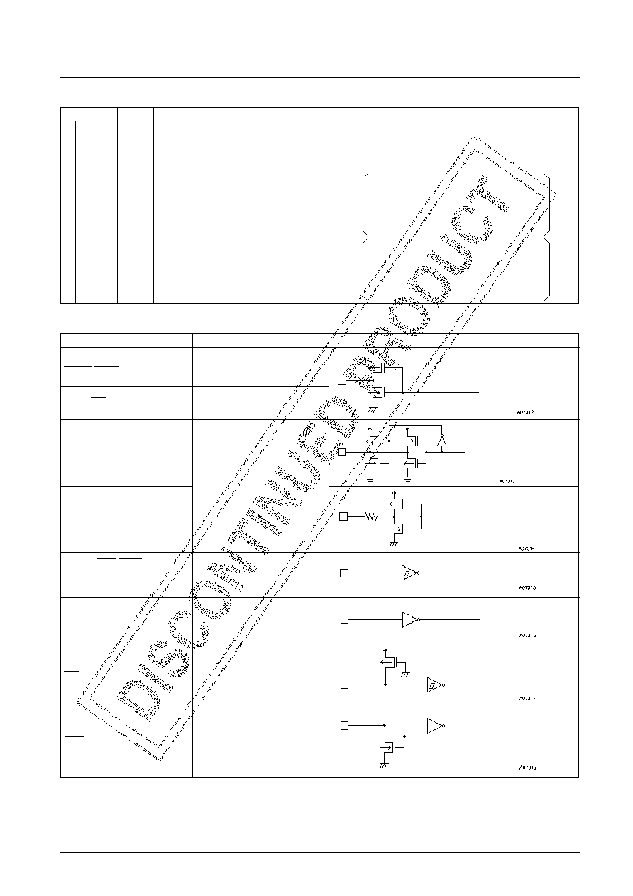
Pin Circuits
Pins
Specifications
Circuit
ASO, LRCKO, BCKO, RAS, CAS,
DREAD, DWRT, FS384O, A0 to A8
TTL output
ADL2, ADL3, ADM2, ADM3, ADR2,
ADR3
Analog output
Schmitt input
DALP, DALN, DARP, DARN
SI, SICK, SIRQ, SRDY, (OSC1)
Low Schmitt input
FS384I, BCKI, ASI, LRCKI
Normal input
TEST1 to TEST5
Input with built-in pull-up resistor
RES
Input with built-in pull-down resistor
SELC, SAIF, SAOF
P3, P4, SIAK
CMOS intermediate current output
Continued on next page.
Output data
Input data
相關(guān)PDF資料 |
PDF描述 |
|---|---|
| LC83200W | SPECIALTY CONSUMER CIRCUIT, PQFP48 |
| LC83210W | SPECIALTY CONSUMER CIRCUIT, PQFP48 |
| LC85632 | LED CLOCK, PDIP30 |
| LC8650T | SPECIALTY CONSUMER CIRCUIT, PDSO24 |
| LC8900KQ | SPECIALTY CONSUMER CIRCUIT, PQFP44 |
相關(guān)代理商/技術(shù)參數(shù) |
參數(shù)描述 |
|---|---|
| LC8390 | 制造商:SANYO 制造商全稱:Sanyo Semicon Device 功能描述:16bits A/D and D/A Converters for Digital Audio Systems |
| LC8390M | 制造商:SANYO 制造商全稱:Sanyo Semicon Device 功能描述:16bits A/D and D/A Converters for Digital Audio Systems |
| LC8395-90 | 制造商:未知廠家 制造商全稱:未知廠家 功能描述:16-Bit Microcontroller |
| LC8395BH | 制造商:未知廠家 制造商全稱:未知廠家 功能描述:16-Bit Microcontroller |
| LC83C152JA | 制造商:未知廠家 制造商全稱:未知廠家 功能描述:8-Bit Microcontroller |
發(fā)布緊急采購(gòu),3分鐘左右您將得到回復(fù)。