- 您現(xiàn)在的位置:買賣IC網(wǎng) > PDF目錄358757 > LC65F1306A* (Sanyo Electric Co.,Ltd.) PDF資料下載
參數(shù)資料
| 型號(hào): | LC65F1306A* |
| 廠商: | Sanyo Electric Co.,Ltd. |
| 文件頁(yè)數(shù): | 3/22頁(yè) |
| 文件大小: | 685K |
第1頁(yè)第2頁(yè)當(dāng)前第3頁(yè)第4頁(yè)第5頁(yè)第6頁(yè)第7頁(yè)第8頁(yè)第9頁(yè)第10頁(yè)第11頁(yè)第12頁(yè)第13頁(yè)第14頁(yè)第15頁(yè)第16頁(yè)第17頁(yè)第18頁(yè)第19頁(yè)第20頁(yè)第21頁(yè)第22頁(yè)
LC65F1306A
No.6829-3/22
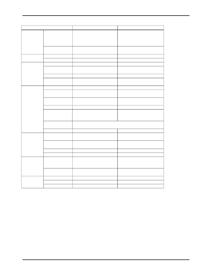
Function Table
Parameter
ROM
LC651306A/04A/02A/01A
6144
×
8 bits (1306A)
4096
×
8 bits (1304A)
2048
×
8 bits (1302A)
1024
×
8 bits (1301A)
256
×
4 bits
(1306A/04A/02A/01A)
81
Supported
1 external, 1 internal
4-bit variable prescaler + 8-bit
timers
8
Standby mode by the HALT
instruction supported
18 I/O port pins
Input and output in 4 or 8 bit
units
LC65F1306A
6144
×
8 bits
Memory
RAM
256
×
4 bits
Instruction set
Table reference
Interrupt
Timer
81
Instructions
Supported
1 external, 1 internal
4-bit variable prescaler + 8-bit
timers
8
Standby mode by the HALT
instruction supported
22 I/O port pins
Input and output in 4 or 8 bit
units
Stack level
Standby function
On-chip
functions
Port number
Serial port
I/O
capacity
Output current
I/O circuit type
voltage
15 V max.
15 V max.
10 mA typ. 20 mA max.
Open drain (N-channel) or
pull-up resistor output option
can be specified in 1- bit unit.
High or low level output can be selected in port unit (ports C and D
only)
Supported
0.92
μ
s (VDD
≥
2.5 V)
10 mA typ. 20 mA max.
Open drain (N-channel)
Output
reset
Square wave output
Minimum
time
Operating
temperature
Supply voltage
Supply current
Oscillator
level
at
I/O ports
Supported
cycle
0.92
μ
s (VDD
≥
3.0 V)
-40
°
C to +85
°
C
0
°
C to +85
°
C (when writing)
-20
°
C to +85
°
C (when reading)
3.0 to 5.5 V
3 mA typ.
RC (800 kHz typ.)
Ceramic (400k, 800k,1MHz,
4MHz)
1/1, 1/3, 1/4
2.5 to 6 V
1.5 mA typ.
RC (800 kHz typ.)
Ceramic (400k, 800k,1MHz,
4MHz)
1/1, 1/3, 1/4
Characteristics
Oscillator
Divider
option
Package
Watchdog timer
OTP
circuit
DIP24S MFP24S SSOP24
Supported
Only DIP24S MFP24S
DIP24S MFP24S
Supported
-
Other items
Note: The above oscillator and oscillator circuit constants are tentative. They will be announced as the recommended circuits
for these microcontrollers are determined. Please confirm the progress of these developments periodically.
相關(guān)PDF資料 |
PDF描述 |
|---|---|
| LC65F1306A | 4-Bit Single-Chip CMOS Microcontroller for Small-Scale Control Applications |
| LC65P1104 | On-Chip UVEPROM 4-Bit Single-Chip Microcontroller |
| LC662106A | Four-Bit Single-Chip Microcontrollers with 4, 6, and 8 KB of On-Chip ROM |
| LC662306A | Four-Bit Single-Chip Microcontrollers with 6 KB of On-Chip ROM(4位單片微控制器(帶6K字節(jié)片上ROM)) |
| LC662308A | Four-Bit Single-Chip Microcontroller with 16 KB of On-Chip OTP PROM |
相關(guān)代理商/技術(shù)參數(shù) |
參數(shù)描述 |
|---|---|
| LC65P0101 | 制造商:未知廠家 制造商全稱:未知廠家 功能描述:Microcontroller |
| LC65P1104 | 制造商:SANYO 制造商全稱:Sanyo Semicon Device 功能描述:One-Time Programmable 4-Bit Single-Chip Microcontroller |
| LC65P29 | 制造商:SANYO 制造商全稱:Sanyo Semicon Device 功能描述:One-Time Programmable 4-Bit Single-Chip Microcontroller |
| LC65P3608 | 制造商:未知廠家 制造商全稱:未知廠家 功能描述: |
發(fā)布緊急采購(gòu),3分鐘左右您將得到回復(fù)。