- 您現(xiàn)在的位置:買賣IC網(wǎng) > PDF目錄358737 > LA76850 (Sanyo Electric Co.,Ltd.) Monolithic Linear IC Black & White Television IC PDF資料下載
參數(shù)資料
| 型號: | LA76850 |
| 廠商: | Sanyo Electric Co.,Ltd. |
| 英文描述: | Monolithic Linear IC Black & White Television IC |
| 中文描述: | 單片線性集成電路黑色 |
| 文件頁數(shù): | 15/31頁 |
| 文件大?。?/td> | 295K |
| 代理商: | LA76850 |
第1頁第2頁第3頁第4頁第5頁第6頁第7頁第8頁第9頁第10頁第11頁第12頁第13頁第14頁當前第15頁第16頁第17頁第18頁第19頁第20頁第21頁第22頁第23頁第24頁第25頁第26頁第27頁第28頁第29頁第30頁第31頁
LA76850
NoA0017-15/31
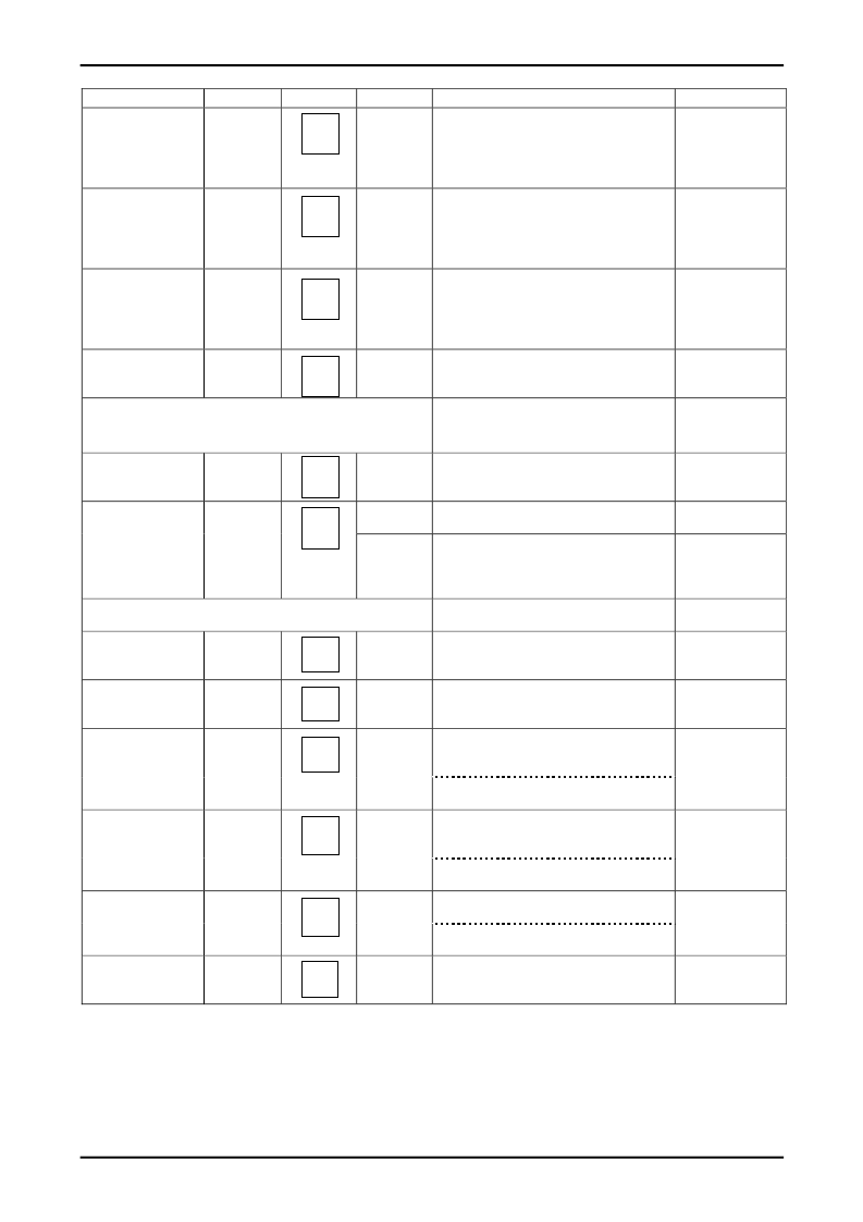
Continued from preceding page.
Input signal
Symbol
Test point
Input signal
Test method
Bus conditions
Y gamma effective
point1
YG1
L-100
Measure the output amplitude (0 to 100 IR) when
the Y gamma is 0 (GAM0). Then set Y gamma to 1
and measure the output amplitude (0 to 100 IR)
again (GAM1).
Calculate YG1 = (GAM1/GAM0)
×
100.
Measure the output amplitude (0 to 100 IR) when
the Y gamma is 0 (GAM0). Then set Y gamma to 2
and measure the output amplitude (0 to 100 IR)
again (GAM2).
Calculate YG2 = (GAM2/GAM0)
×
100.
Measure the output amplitude (0 to 100 IR) when
the Y gamma is 0 (GAM0). Then set Y gamma to 3
and measure the output amplitude (0 to 100 IR)
again (GAM3).
Calculate YG3 = (GAM3/GAM0)
×
100.
Measure the DC level (RGBBLK V) for the output
signal’s blanking period.
Y GAMMA = 1
Y gamma effective
point12
YG2
L-100
Y GAMMA = 2
Y gamma effective
point1
YG3
L-100
Y GAMMA = 3
Horizontal/vertical
blanking output
level
[OSD block]
RGBBLK
L-100
Bus control bit conditions:
Contrast = 63, Brightness = 63
Contrast: 0111111
Brightness:
0111111
OSD
Fast SW threshold
FSTH
L-0
O-2
Apply voltage to pin 15 and measure the voltage at
pin 15 at the point where the output signal switches
to the OSD signal.
Measure the output signal’s 50IRE amplitude
(CNTCB Vp-p).
Measure the OSD output amplitude
(OSDHB Vp-p).
Calculate OSDH =
50
×
(OSDHB/CNTCB)
Bus control bit conditions: Contrast = 127
Pin 14A: O-2
applied
L-50
Osd cont = 0111111
Digital osd = 1
Pin 15: 3.5V
Pin 14A: O-2
applied
OSD output
level
OSDH
L-0
O-2
[Y output block] (Cutoff, drive block)
Contrast:
1111111
Brightness:
01111111
Brightness control
(normal)
BRT63
L-0
Measure the 0IRE DC levels of the
respective output signals of Y output
(17)
Measure the 0IRE DC level of the output Signal of
Y output (17) and assign the Measured value to
BRTPC.
Measure the 0IRE DC level of the output Signal of
Y output (17) and assign the Measured value to
BRTPH.
Calculate BRT127 =
50
×
(BRTPH-BRTPC)/CNTHB.
Measure the 0IRE DC level of the output
Signal of Y output (17) and assign the
Measured value to BRTPL.
Calculate BRT0 =
50
×
(BRTPL-BRTPC)/CNTHB.
Measure the 0IRE DC levels (BTPM V) of the
respective output signals of Y output (17).
Vbiassns = (BRTPH-BTPM)/127
Brightness control
(normal-H)
BRT63H
L-0
Brightness:
0111111
Sub Bias: 1111111
Brightness:
1111111
Sub Bias: 1111111
Brightness control
(max)
BRT127
L-0
Brightness control
(min)
BRT0
L-0
Brightness:
0000000
Sub Bias: 1111111
Bright control
resolution
Vsiassns
L-50
Brightness:
0000000
Sub Bias:
1111111
Brightness:
0111111
Sub Bias: 0000000
Sub-bias control
resolution
Vsbiassns
L-50
Measure the 0IRE DC levels (SBTPM V) of the
respective output signals of Y output (17).
Vsbiassns = (BRTPCH-SBTPM)/127
17
17
17
17
17
17
17
17
17
17
17
17
相關PDF資料 |
PDF描述 |
|---|---|
| LA7685J | PAL/NTSC Single-chip Color Television Signal Processing Circuit |
| LA7688 | Single-Chip CTV Signal-Processing Circuit for PAL and NTSC Formats |
| LA76930 | LA76930 |
| LA7696 | Color TV ON-Screen Display Interface |
| LA7698 | Color-Difference Signal Correction IC for Color TVs |
相關代理商/技術參數(shù) |
參數(shù)描述 |
|---|---|
| LA7685J | 制造商:SANYO 制造商全稱:Sanyo Semicon Device 功能描述:PAL/NTSC Single-chip Color Television Signal Processing Circuit |
| LA7688 | 制造商:SANYO 制造商全稱:Sanyo Semicon Device 功能描述:Single-Chip CTV Signal-Processing Circuit for PAL and NTSC Formats |
| LA76922M | 制造商:SANYO 制造商全稱:Sanyo Semicon Device 功能描述:Signal-Processing IC with Integrated Microcontroller |
| LA76930 | 制造商:SANYO 制造商全稱:Sanyo Semicon Device 功能描述:LA76930 |
| LA76931J7FB-E | 制造商:ON Semiconductor 功能描述:SIGNAL PROCESSING FOR CRT - Ammo Pack 制造商:ON Semiconductor 功能描述:FNFLD / SIGNAL PROCESSING FOR CRT |
發(fā)布緊急采購,3分鐘左右您將得到回復。