- 您現(xiàn)在的位置:買賣IC網(wǎng) > PDF目錄43901 > L6995STR (STMICROELECTRONICS) SWITCHING CONTROLLER, PDSO20 PDF資料下載
參數(shù)資料
| 型號: | L6995STR |
| 廠商: | STMICROELECTRONICS |
| 元件分類: | 穩(wěn)壓器 |
| 英文描述: | SWITCHING CONTROLLER, PDSO20 |
| 封裝: | MO-153-AC, TSSOP-20 |
| 文件頁數(shù): | 2/26頁 |
| 文件大小: | 427K |
| 代理商: | L6995STR |
第1頁當(dāng)前第2頁第3頁第4頁第5頁第6頁第7頁第8頁第9頁第10頁第11頁第12頁第13頁第14頁第15頁第16頁第17頁第18頁第19頁第20頁第21頁第22頁第23頁第24頁第25頁第26頁

L6995S
10/26
be supposed linear function of the time.
Eq 8
so the output voltage is given by:
Eq 9
calling Vout as the Vout final value, the output charging time can be estimated as:
Eq 10
the minimum CSS value is given imposing this condition:
Eq 11
Tout =Tuvp
4.5 Current limit
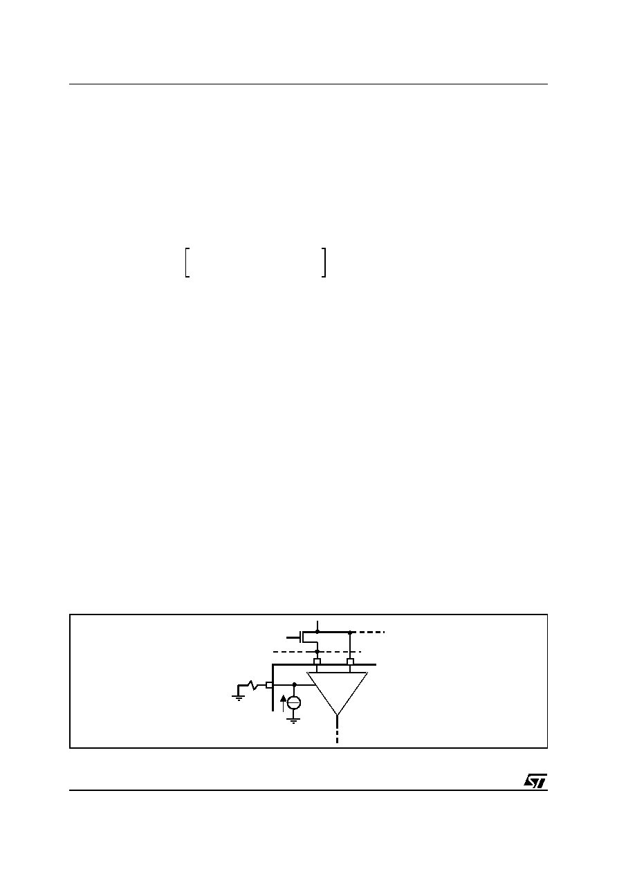
The current limit comparator senses the inductor current through the low side MOSFET RDSON drop and com-
pares this value with the ILIM pin voltage value. While the current is above the current limit value, the control
inhibits the one-shot start.
To properly set the current limit threshold, it should be noted that this is a valley current limit. Average current
depends on the inductor value, VIN VOUT and switching frequency.
The average output current in current limit is given by:
Eq 12
Thus, to set the current threshold, choose RILIM according to the following equation:
Eq 13
In current limit the system keeps the current constant until the output voltage meets the undervolatge threshold.
The system is capable to sink current, but it has not a negative current limit.
The system accuracy is function of the exactness of the resistance connected to ILIM pin and the low side MOS-
FET RDSON accuracy. Moreover the voltage on ILIM pin must range between 10mV and 2V to ensure the sys-
tem linearity.
Figure 9. Current limit schematic
I
L t,CSS
()
R
ilim /Rdson
K
C
I
SS t
()
V
SS
C
SS
()
-------------------------------------------------------------------
=
V
out t,CSS
()
Qt,C
SS
()
C
out
-------------------------
R
ilim/Rdson
K
C
I
SS
t
2
()
C
out
V
SS
C
SS 2
()
----------------------------------------------------------------------
==
I
out CSS
()
V
out
C
out
V
SS
C
SS
2
()
R
ilim /Rdson
K
C
I
SS
()
----------------------------------------------------------------------------
0.5
=
I
OUT
CL
I
max valley
I
2
-----
+
=
I
max valley
R
ILim
Rds
on
-----------------
I
Lim
5.2
----------
=
Positive current limit
R
ILIM
5A
Current
Comparator
To
logic
PGN
D
PHASE
To inductor
LS
相關(guān)PDF資料 |
PDF描述 |
|---|---|
| L6997D | SWITCHING CONTROLLER, PDSO20 |
| L6997DTR | SWITCHING CONTROLLER, PDSO20 |
| L7200 | DISK DRIVE MOTOR CONTROLLER, 2.6 A, PQFP64 |
| L7250 | VOICE COIL MOTOR CONTROLLER, PQFP64 |
| L7980A | 3.5 A SWITCHING REGULATOR, 1000 kHz SWITCHING FREQ-MAX, PDSO8 |
相關(guān)代理商/技術(shù)參數(shù) |
參數(shù)描述 |
|---|---|
| L6996 | 功能描述:DC/DC 開關(guān)控制器 Step-Down Contrllr RoHS:否 制造商:Texas Instruments 輸入電壓:6 V to 100 V 開關(guān)頻率: 輸出電壓:1.215 V to 80 V 輸出電流:3.5 A 輸出端數(shù)量:1 最大工作溫度:+ 125 C 安裝風(fēng)格: 封裝 / 箱體:CPAK |
| L6996-1 | 制造商:Johanson 功能描述:TUNING ROTOR |
| L6996-13 | 制造商:Johanson Manufacturing 功能描述:TUNING ELEMENT |
| L6996-16 | 制造商:Johanson Manufacturing 功能描述:TUNING ELEMENT |
| L6996-17 | 制造商:Johanson Manufacturing 功能描述:TUNING ELEMENT |
發(fā)布緊急采購,3分鐘左右您將得到回復(fù)。