- 您現(xiàn)在的位置:買賣IC網(wǎng) > PDF目錄97995 > L6280 (STMICROELECTRONICS) STEPPER MOTOR CONTROLLER, 4.4 A, PQCC44 PDF資料下載
參數(shù)資料
| 型號(hào): | L6280 |
| 廠商: | STMICROELECTRONICS |
| 元件分類: | 運(yùn)動(dòng)控制電子 |
| 英文描述: | STEPPER MOTOR CONTROLLER, 4.4 A, PQCC44 |
| 封裝: | PLASTIC, LCC-44 |
| 文件頁(yè)數(shù): | 5/26頁(yè) |
| 文件大?。?/td> | 8983K |
| 代理商: | L6280 |
第1頁(yè)第2頁(yè)第3頁(yè)第4頁(yè)當(dāng)前第5頁(yè)第6頁(yè)第7頁(yè)第8頁(yè)第9頁(yè)第10頁(yè)第11頁(yè)第12頁(yè)第13頁(yè)第14頁(yè)第15頁(yè)第16頁(yè)第17頁(yè)第18頁(yè)第19頁(yè)第20頁(yè)第21頁(yè)第22頁(yè)第23頁(yè)第24頁(yè)第25頁(yè)第26頁(yè)

A0 A1
1 1 This configuration is used to cause an incre-
ment or a decrement of a DAC. Right or
left DAC and inc/dec are selected by
D0 to D3 value.
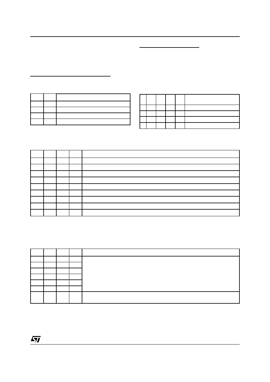
A2, A3 DECODING (Channel Selection)
Every time a command or a initialization is sent to
the L6280, a channel must be selected. This is
done via A2 and A3 according to the table.
A2
A3
0
1
Select channel 2
1
0
Select channel 1
1
Select channel 3
0
Used only with keyword and watchdog
D0 to D3 DECODING (Datas)
The meaning of D0,
D3 changes according to
the value of A0, A1
A0 A1
0 0 When A0, A1 are in this configuration, and
channel 1 or 2 is selected, the data appear-
ing in D0 to D3 set the output power stage
configuration to fit the chosed load accord-
ing to the allowed Truth Table. There is no
need to configure channel 3.
D3
D2
D1
D0
Possible configurations for
channels 1 and 2
0000
Null (power disabled)
a
0001
Unipolar motor
b
0010
Full Bridge
c
0011
Dual Half Bridge
b) Full Bridge Configuration
a) Unipolar Motor Configuration
In this configuration D0 to D3 directly drive the low side drives:
D3
D2
D1
D0
Configurations
00
Low side drivers 1,2,3,4 OFF
00
01
Low side drivers 2,3,4 OFF
Low side driver 1 ON
00
10
Low side drivers 1,3,4 OFF
Low side driver 2 ON
01
00
Low side drivers 1,2,4 OFF
Low side driver 3 ON
01
Low side drivers 2,4 OFF
Low side drivers 1,3 ON
01
10
Low side drivers 1,4 OFF
Low side drivers 2,3 ON
10
00
Low side drivers 1,2,3 OFF
Low side driver 4 ON
10
01
Low side drivers 2,3 OFF
Low side drivers 1,4 ON
10
Low side drivers 1,3 OFF
Low side driver 2,4 ON
The following configurations are not allowed: the microprocessor does not to generate them otherwise
they can cause faulty operations.
D3
D2
D1
D0
00
11
Always not allowed
01
11
10
11
00
11
01
11
10
11
This configuration is not allowed when driving a unipolar motor and it is
permitted only to drive a high current solenoid.
L6280
13/26
相關(guān)PDF資料 |
PDF描述 |
|---|---|
| L6285S | STEPPER MOTOR CONTROLLER, 2 A, PDIP42 |
| L6470HTR | STEPPER MOTOR CONTROLLER, 7 A, PDSO28 |
| L6562DTR | 0.8 A POWER FACTOR CONTROLLER, PDSO8 |
| L6562D | 0.8 A POWER FACTOR CONTROLLER, PDSO8 |
| L6563HTR | POWER FACTOR CONTROLLER, PDSO16 |
相關(guān)代理商/技術(shù)參數(shù) |
參數(shù)描述 |
|---|---|
| L6281B12D | 制造商:ST MICRO 功能描述:New |
| L6282-3.2E | 制造商:STMicroelectronics 功能描述:L6282-3.2E |
| L6283-1.2 | 制造商:STMicroelectronics 功能描述:ELECTRONIC COMPONENT |
| L6283-1.3 | 制造商:STMicroelectronics 功能描述:ELECTRONIC COMPONENT |
| L6285 | 制造商:STMICROELECTRONICS 制造商全稱:STMicroelectronics 功能描述:3 CHANNELS MULTIPOWER SYSTEM |
發(fā)布緊急采購(gòu),3分鐘左右您將得到回復(fù)。