- 您現(xiàn)在的位置:買賣IC網(wǎng) > PDF目錄384519 > ISD5116 (WINBOND ELECTRONICS CORP) Single-Chip Voice Record/Playback Device Up to 16-Minute Duration with Digital Storage Capability PDF資料下載
參數(shù)資料
| 型號: | ISD5116 |
| 廠商: | WINBOND ELECTRONICS CORP |
| 英文描述: | Single-Chip Voice Record/Playback Device Up to 16-Minute Duration with Digital Storage Capability |
| 中文描述: | 單芯片語音記錄/播放設(shè)備與數(shù)字存儲能力為16分鐘時間 |
| 文件頁數(shù): | 11/57頁 |
| 文件大小: | 735K |
| 代理商: | ISD5116 |
第1頁第2頁第3頁第4頁第5頁第6頁第7頁第8頁第9頁第10頁當(dāng)前第11頁第12頁第13頁第14頁第15頁第16頁第17頁第18頁第19頁第20頁第21頁第22頁第23頁第24頁第25頁第26頁第27頁第28頁第29頁第30頁第31頁第32頁第33頁第34頁第35頁第36頁第37頁第38頁第39頁第40頁第41頁第42頁第43頁第44頁第45頁第46頁第47頁第48頁第49頁第50頁第51頁第52頁第53頁第54頁第55頁第56頁第57頁
October 2000
Page 10
9. Slave responds with Lower Address byte of internal address register (A[4:0] will always return set to 0.)
10. Host sends a NO ACK to Slave, then executes I
2
C STOP
Note that the processor could have sent an I
2
C STOP after the Status Word data transfer and aborted the
transfer of the Address bytes.
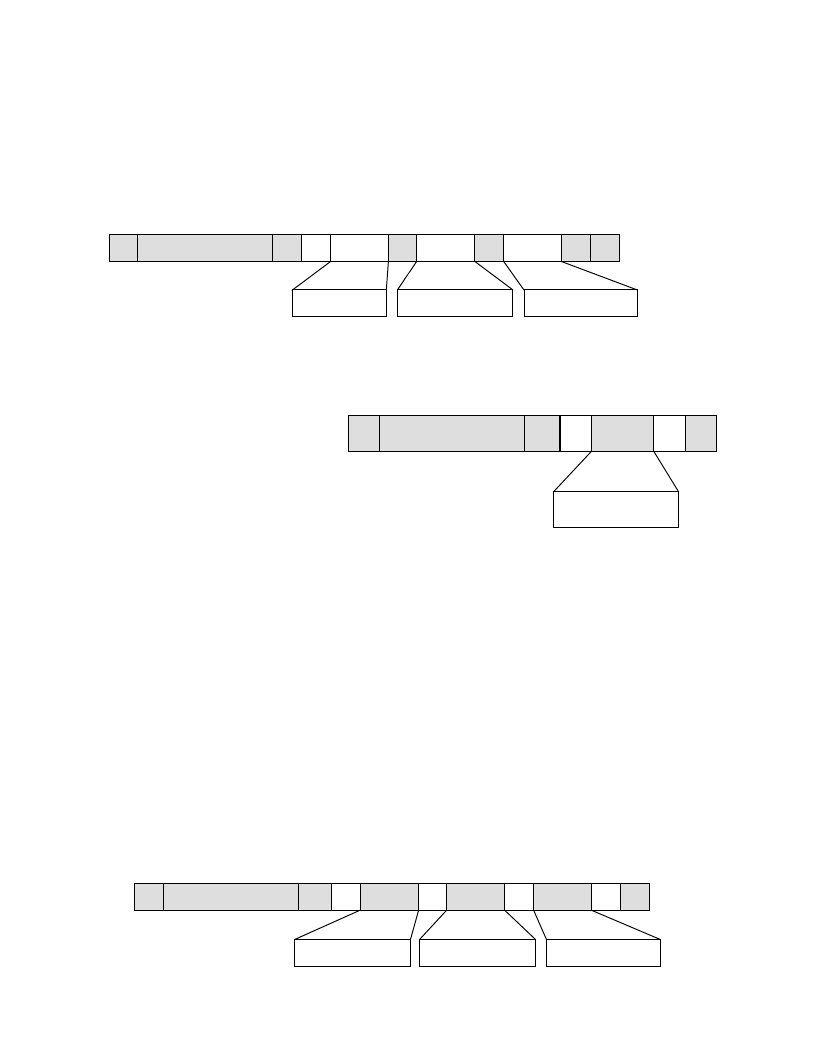
A graphical representation of this operation is found below. See the caption box above for more
explanation.
2. LOAD COMMAND BYTE REGISTER (SINGLE BYTE LOAD): A single byte may be written to the
Command Byte Register in order to power up the device, start or stop Analog Record (if no address
information is needed), or do a Message Cueing function. The Command Byte Register is loaded as
follows:
1. Host executes I
2
C START
2. Send Slave Address with R/W bit = “0” (Write) [80h]
3. Slave responds back with an ACK.
4. Wait for SCL to go HIGH
5. Host sends a command byte to Slave
6. Slave responds with an ACK
7. Wait for SCL to go HIGH
8. Host executes I
2
C STOP
3. LOAD COMMAND BYTE REGISTER (ADDRESS LOAD): For the normal addressed mode the
Registers are loaded as follows:
1. Host executes I
2
C START
2. Send Slave Address with R/W bit = “0” (Write)
3. Slave responds back with an ACK.
4. Wait for SCL to go HIGH
5. Host sends a byte to Slave - (Command Byte)
6. Slave responds with an ACK
7. Wait for SCL to go HIGH
8. Host sends a byte to Slave - (High Address Byte)
9. Slave responds with an ACK
10. Wait for SCL to go HIGH
11. Host sends a byte to Slave - (Low Address Byte)
12. Slave responds with an ACK
13. Wait for SCL to go HIGH
14. Host executes I
2
C STOP
S
SLAVE ADDRESS
A
A
DATA
P
R
DATA
DATA
A
N
Status
High Addr.
Low Addr.
S
SLAVE ADDRESS
A
DATA
P
W
Command Byte
A
S
SLAVE ADDRESS
A
P
W
Command
DATA
A
DATA
A
DATA
A
High Addr.
Low Addr.
發(fā)布緊急采購,3分鐘左右您將得到回復(fù)。