- 您現(xiàn)在的位置:買賣IC網(wǎng) > PDF目錄385438 > IR1110 (International Rectifier) SOFT START CONTROLLER IC PDF資料下載
參數(shù)資料
| 型號: | IR1110 |
| 廠商: | International Rectifier |
| 英文描述: | SOFT START CONTROLLER IC |
| 中文描述: | 軟起動(dòng)控制器芯片 |
| 文件頁數(shù): | 7/32頁 |
| 文件大小: | 227K |
| 代理商: | IR1110 |
第1頁第2頁第3頁第4頁第5頁第6頁當(dāng)前第7頁第8頁第9頁第10頁第11頁第12頁第13頁第14頁第15頁第16頁第17頁第18頁第19頁第20頁第21頁第22頁第23頁第24頁第25頁第26頁第27頁第28頁第29頁第30頁第31頁第32頁

7
IR1110
ADVANCE INFORMATION
www.irf.com
Notes for AC Electrical Characteristics
Note 1)
Delay is proportional to the capacitor values with minimum allowed value of C
3PH
= .01
μ
F
Note 2)
Depends on C
PKLL
charge condition
Note 3)
C
UVLO
= .1
μ
F, C
1PH
= .001
μ
F. Increasing C
UVLO
increases the delay/response time of the 1phase lockout.
Note 4)
Pulse width is proportional to C1PH. Maximum allowed values of C
1PH
is .001
μ
F.
Note 5)
Power up delay is set by C
UVLO
or by V
DD
rise time whichever takes longer. In this condition, V
DD
rise time must
not be less than 100msec, and 1-phase shutdown must be enabled. If this is less than 100msec or 1-phase shut
down is disabled, C
UVLO
must be increased to 0.22
μ
F in order to increase the undervoltage lockout time to greater
than 100msec. See Note 3) above on additional effect of increasing C
UVLO
.
Note 6)
Ramp time is proportional to the capacitor value.
Note 7)
This value corresponds approximately to 15V minimum SCR firing voltage. For 15V minimum SCR firing voltage,
(R
SG2
/R
SG1
) X V
DD
= (R
U2
/R
U1
) X 15.
Note 8)
PPUBAL applies to steady operation, is deviation of any firing point to closest balanced set of firing points.
Note 9)
Firing angle is defined with respect to zero delay (ie. max output voltage.
System Operating Characteristics and Specifications
All peripheral component values are those listed in the recommended operating condition unless otherwise specified.
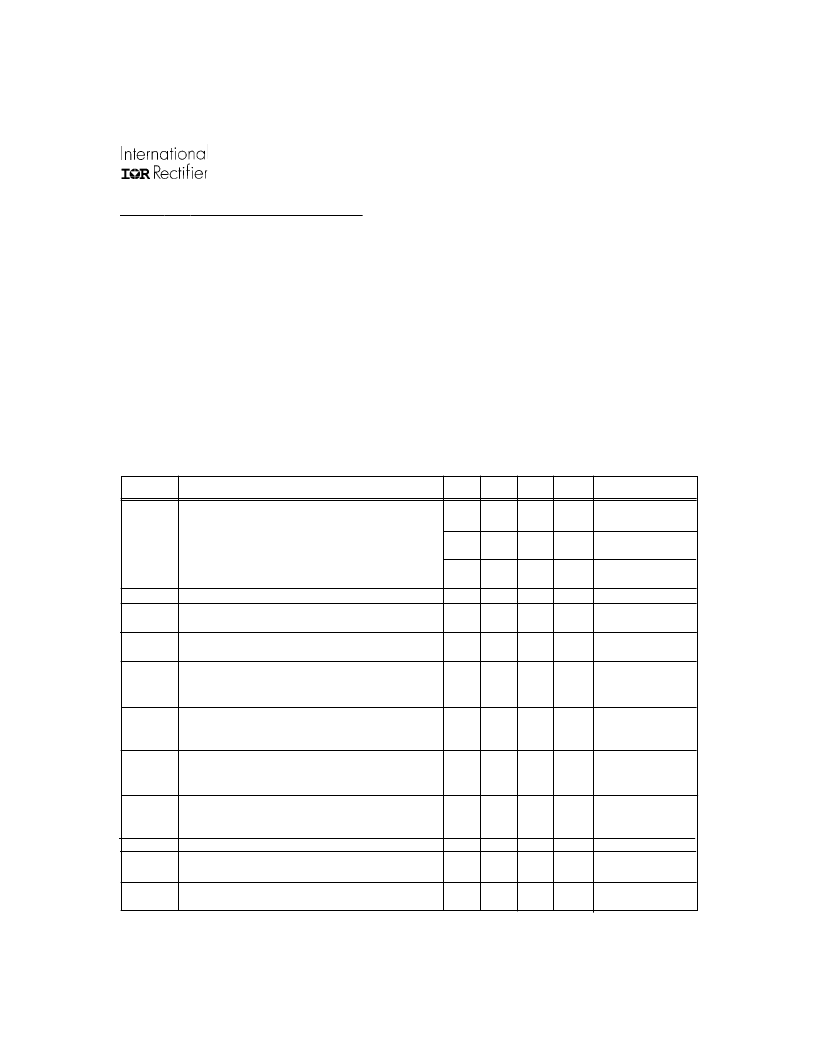
Symbol
V
AC
Definition
Min.
80
Typ. Max. Units Test Conditions
120
140
Line-to-line AC voltage range (1%)
Ru1,Rv1,Rw1=475K
R
POS1
,R
NEG1
=453K
Ru1,Rv1,Rw19537K
R
POS1
,R
NEG1
=887K
Ru1,Rv1,Rw1=2X953K
R
POS1
,R
NEG1
=887K
161
230
276
V
RMS
322
460
552
f
LINE
V
BRANGE
V
BREG
V
BRES
Input line frequency
DC bus voltage controllable range
DC bus voltage regulation
DC bus voltage step response time
47
35
—-
—-
50/60
—-
2
100
63
99.8
—-
—-
Hz
%
%
msec
V
BREF
=1.4V to 4V
V
BUS
=35% to 100%
Note 6
C
RAMP
= 1
μ
F
R
RAMP
= 82k
(Note 7)
C
RAMP
= 1
μ
F
R
RAMP
= 82k
(Note 7)
C
RAMP
= 1
μ
F
C
UVLO
= 0.1
μ
F
Note 9)
Voltage drop below
the reference voltage
at B
DIP2
pin
°
Figure 2, Note 14
msec
1PHEN = V
DD
t
RAMP1
DC bus voltage ramp up time at power up
—
150
—-
msec
t
RAMP2
DC bus voltage ramp up time at power dip
ride through
—-
75
—-
msec
td
PWR
Power up delay time before ramp up
—-
190
—-
msec
td
DIP1
Delay time to start ramp-up after recovery from
a transient loss of line voltage
15
msec
a
FIRE
td
1PHS
Firing angle range
Delay time to shutdown SCR firing pulses after
loss of one phase input
Delay time to start ramp-up after recovery from a
loss of one phase input
1.5
15
—-
—-
160
30
td
1PHE
—-
30
—-
msec
1PHEN = V
DD
相關(guān)PDF資料 |
PDF描述 |
|---|---|
| IR1175 | Synchronous Rectifier Driver |
| IR140CSP | Flipky |
| IR2103 | HALF-BRIDGE DRIVER |
| IR2103S | HALF-BRIDGE DRIVER |
| IR3311 | PROGRAMMABLE CURRENT SENSING HIGH SIDE SWITCH |
相關(guān)代理商/技術(shù)參數(shù) |
參數(shù)描述 |
|---|---|
| IR11-21C | 制造商:Everlight Electronics Co 功能描述:LED IrLED 940nm 2-Pin Chip LED Box 制造商:Everlight Electronics Co 功能描述:IRED, , 1206, SMD - Tape and Reel |
| IR11-21C/TR8 | 功能描述:紅外發(fā)射源 Infrared LED RoHS:否 制造商:Fairchild Semiconductor 波長:880 nm 射束角:+/- 25 輻射強(qiáng)度: 最大工作溫度:+ 100 C 最小工作溫度:- 40 C 封裝 / 箱體:Side Looker 封裝:Bulk |
| IR11-21C-TR8 | 制造商:EVERLIGHT 制造商全稱:Everlight Electronics Co., Ltd 功能描述:Infrared LED With Inner Lens |
| IR11452SPBF | 功能描述:IC PFC ONE CYCLE CONTROL 8SOIC RoHS:是 類別:未定義的類別 >> 其它 系列:* 標(biāo)準(zhǔn)包裝:1 系列:* 其它名稱:MS305720A |
| IR11452STRPBF | 功能描述:功率因數(shù)校正 IC 9999V 999A SOIC RoHS:否 制造商:Fairchild Semiconductor 開關(guān)頻率:300 KHz 最大功率耗散: 最大工作溫度:+ 125 C 安裝風(fēng)格:SMD/SMT 封裝 / 箱體:SOIC-8 封裝:Reel |
發(fā)布緊急采購,3分鐘左右您將得到回復(fù)。