- 您現(xiàn)在的位置:買賣IC網(wǎng) > PDF目錄385404 > HT82M99EE (Holtek Semiconductor Inc.) USB Mouse Encoder 8-Bit MCU PDF資料下載
參數(shù)資料
| 型號(hào): | HT82M99EE |
| 廠商: | Holtek Semiconductor Inc. |
| 英文描述: | USB Mouse Encoder 8-Bit MCU |
| 中文描述: | USB鼠標(biāo)編碼器8位微控制器 |
| 文件頁(yè)數(shù): | 23/47頁(yè) |
| 文件大小: | 336K |
| 代理商: | HT82M99EE |
第1頁(yè)第2頁(yè)第3頁(yè)第4頁(yè)第5頁(yè)第6頁(yè)第7頁(yè)第8頁(yè)第9頁(yè)第10頁(yè)第11頁(yè)第12頁(yè)第13頁(yè)第14頁(yè)第15頁(yè)第16頁(yè)第17頁(yè)第18頁(yè)第19頁(yè)第20頁(yè)第21頁(yè)第22頁(yè)當(dāng)前第23頁(yè)第24頁(yè)第25頁(yè)第26頁(yè)第27頁(yè)第28頁(yè)第29頁(yè)第30頁(yè)第31頁(yè)第32頁(yè)第33頁(yè)第34頁(yè)第35頁(yè)第36頁(yè)第37頁(yè)第38頁(yè)第39頁(yè)第40頁(yè)第41頁(yè)第42頁(yè)第43頁(yè)第44頁(yè)第45頁(yè)第46頁(yè)第47頁(yè)

HT82M99EE/HT82M99AE
Rev. 1.00
23
February 8, 2006
Therearesometimingconstrainsandusagesillustratedhere.BysettingtheMISCregister,theMCUcanperformread-
ing,writingandclearingactions.TherearesomeexamplesshowninthefollowingtableforendpointFIFOreading,writ-
ing and clearing.
Actions
MISC Setting Flow and Status
Read FIFO0 sequence
00H
and check if not ready (01H)
01H
delay of 2 s, check 41H
read* from FIFO0 register
02H
03H
Write FIFO1 sequence
0AH
check if not ready (0BH)
0BH
delay of 2 s, check 4BH
write* to FIFO1 register and
09H
08H
Check whether FIFO0 can be read or not
00H
01H
delay of 2 s, check 41H (if ready) or 01H (if not ready)
00H
CheckwhetherFIFO1canbewrittentoornot
0AH
0BH
delay of 2 s, check 4BH (if ready) or 0BH (if not ready)
0AH
Write 0-sized packet sequence to FIFO 0
02H
03H
delay of 2 s, check 43H
01H
00H
Note: *: There are 2 s gap existing between 2 reading actions or between 2 writing actions
Register Name
R/W
Register Address
Bit7~Bit0
FIFO 0
R/W
01001000B
Data7~Data0
FIFO 1
R/W
01001001B
Data7~Data0
FIFO Register Address Table
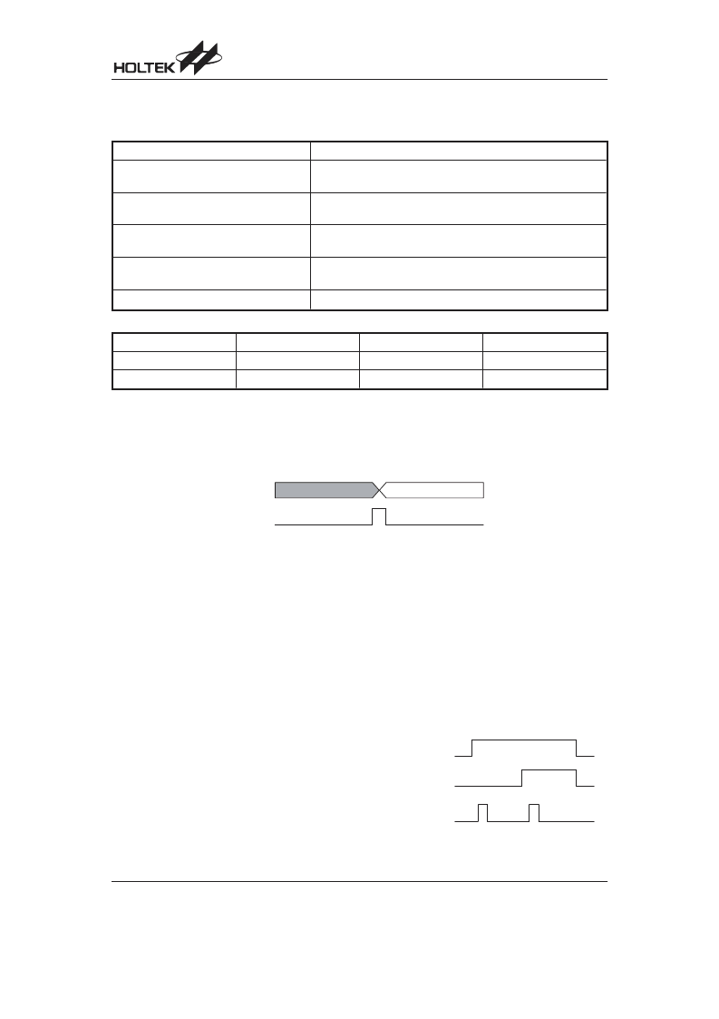
USB Active Pipe Timing
TheUSBactivepipeaccessedbythehostcannotbeusedbytheMCUsimultaneously.Whenthehostfinishesitswork,
the signal, a USB_INT will be produced to tell the MCU that the pipe can be used and the acted pipe No. will be shown
in the signal, ACT_PIPE as well. The timing is illustrated in the Figure below.
USB Active Pipe Timing
- B
B
" (
# (
Suspend Wake-Up and Remote Wake-Up
If there is no signal on the USB bus for over 3ms, the
HT8M99E will go into a suspend mode. The Suspend
line (bit 0 of the USC) will be set to 1 and a USB interrupt
is triggered to indicate that the HT8M99E should jump to
the suspend state to meet the 500 AUSB suspend cur-
rent spec.
In order to meet the 500 A suspend current, the pro-
grammer should disable the USB clock by clearing the
USBCKEN (bit3 of the SCC) to 0 . The suspend cur-
rent is 400 A.
The user can also further decrease the suspend current
to 250 A by setting the SUSP2 (bit4 of the SCC). But if
the SUSP2 is set, the user has to make sure not to en-
able the LVR OPT option, otherwise the HT8M99E will
be reset.
When the resume signal is sent out by the host, the
HT8M99E will wake-up the MCU by USB interrupt and
the Resume line (bit 3 of the USC) is set. In order to
make the HT8M99E function properly, the programmer
must set the USBCKEN (bit 3 of the SCC) to 1 and clear
the SUSP2 (bit4 of the SCC). Since the Resume signal
will be cleared before the Idle signal is sent out by the
host and the Suspend line (bit 0 of the USC) is going to
0 . So when the MCU is detecting the Suspend line
(bit0 of the USC), the Resume line should be remem-
bered and taken into consideration.
After finishing the resume signal, the suspend line will
go inactive and a USB interrupt is triggered. The follow-
ing is the timing diagram:
- (
"
(
,
- B
相關(guān)PDF資料 |
PDF描述 |
|---|---|
| HT82M99E | USB Mouse Encoder 8-Bit OTP MCU |
| HT82M99E-18 | USB Mouse Encoder 8-Bit OTP MCU |
| HT82M99E-20 | USB Mouse Encoder 8-Bit OTP MCU |
| HT82M9AAE | USB Mouse Encoder 8-Bit MCU with EEPROM |
| HT82M9AEE | USB Mouse Encoder 8-Bit MCU with EEPROM |
相關(guān)代理商/技術(shù)參數(shù) |
參數(shù)描述 |
|---|---|
| HT82M99EE_08 | 制造商:HOLTEK 制造商全稱:Holtek Semiconductor Inc 功能描述:USB Mouse Encoder 8-Bit MCU |
| HT82M9AA | 制造商:HOLTEK 制造商全稱:Holtek Semiconductor Inc 功能描述:USB Mouse Encoder 8-Bit MCU |
| HT82M9AAE | 制造商:HOLTEK 制造商全稱:Holtek Semiconductor Inc 功能描述:USB Mouse Encoder 8-Bit MCU with EEPROM |
| HT82M9AE | 制造商:HOLTEK 制造商全稱:Holtek Semiconductor Inc 功能描述:USB Mouse Encoder 8-Bit MCU |
| HT82M9AE_09 | 制造商:HOLTEK 制造商全稱:Holtek Semiconductor Inc 功能描述:USB Mouse Encoder 8-Bit MCU |
發(fā)布緊急采購(gòu),3分鐘左右您將得到回復(fù)。