- 您現(xiàn)在的位置:買賣IC網(wǎng) > PDF目錄385398 > HT36A0 (Holtek Semiconductor Inc.) 8-Bit Music Synthesizer MCU PDF資料下載
參數(shù)資料
| 型號: | HT36A0 |
| 廠商: | Holtek Semiconductor Inc. |
| 英文描述: | 8-Bit Music Synthesizer MCU |
| 中文描述: | 8位微控制器音樂合成器 |
| 文件頁數(shù): | 18/23頁 |
| 文件大小: | 257K |
| 代理商: | HT36A0 |
R vs F Characteristics curve
HT36A0
Rev. 1.20
18
June 18, 2003
The PCM code definition
The HT36A0 can only solve the voice format of the
signed 8-bit raw PCM. And the MCU will take the voice
code 80H as the end code.
So each PCM code section must be ended with the end
code 80H.
D/A Converter Interface
HT36A0 provides the IIS serial data format to support the
multiple D/A converters, one bit clock output and a word
clock signal for left/right stereo serial data transmission.
Clock Signal
The bit clock output signals DCK are used to synchronize
the IIS serial data.
The word clock signal LOAD divides the serial data into
left channel and right channel data for two-way audio out-
put.
LOAD
The word clock signal LOAD is used for IIS serial data.
The stereo serial data consists of 16-channel sound
generator.
On IIS format, a H state on LOAD is used for the
right channel, and a L state is used for the left
channel.
DCK
DCK bit clock is the clock source for the signal.
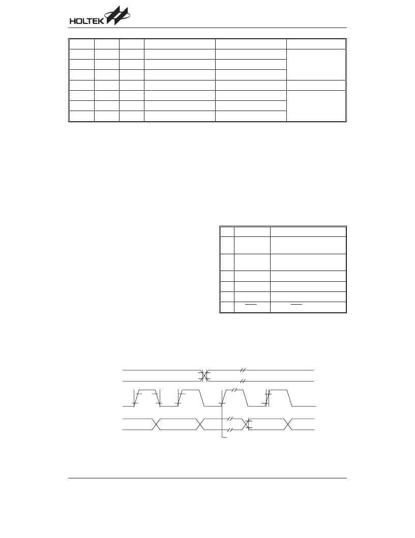
Stereo Serial Data Format
The audio output data is in serial mode with 16 bit digi-
tal signal and LSB first output. There is a high sam-
pling rate of 50kHz when the system clock is 12.8MHz
and with two channel outputs for Right/Left channel.
HT36A0 provides only one serial data format as IIS
mode. The user could directly connect a D/Aconverter
which can accept the IIS serial data format, like
HT82V731.
Mask Option
No. Mask Option
Function
1
WDT source
On-chip RC/Instruction clock/
disable WDT
2
CLRWDT
times
One time, two times
(CLR WDT1/WDT2)
3
Wake-up
PA only
4
Pull-High
PA, PB, PC, PD input
5
OSC mode
Crystal or Resistor type
6
I/O DAC pin
PD1~3 DAC pin selection
E
"
'
& "
"
"
=
.
4
&
0
D/A converter timing
A_R
ENV1
ENV0
Volume Control Bit
Control Bit Final Value
Mode
0
0
0
VL2~0, VR2~0
111b
Release mode
0
0
1
VL1~0, VR1~0
11b
0
1
0
VL0, VR0
1b
x
1
1
No Bit
unchanged
No change mode
1
0
0
VL2~0, VR2~0
000b
Attach mode
1
0
1
VL1~0, VR1~0
00b
1
1
0
VL0, VR0
0b
Envelope type definition
相關PDF資料 |
PDF描述 |
|---|---|
| HT36A1 | Music Synthesizer 8-Bit MCU |
| HT36A2 | 8-Bit Music Synthesizer MCU |
| HT36A3 | 8-Bit Music Synthesizer MCU |
| HT36A4 | 8-Bit Music Synthesizer MCU |
| HT3810 | 128 NOTE MELODY GENERATORS |
相關代理商/技術參數(shù) |
參數(shù)描述 |
|---|---|
| HT36A0(48DIP) | 制造商:未知廠家 制造商全稱:未知廠家 功能描述:Microcontroller |
| HT36A1 | 制造商:HOLTEK 制造商全稱:Holtek Semiconductor Inc 功能描述:Music Synthesizer 8-Bit MCU |
| HT36A2 | 制造商:HOLTEK 制造商全稱:Holtek Semiconductor Inc 功能描述:8-Bit Music Synthesizer MCU |
| HT36A3 | 制造商:HOLTEK 制造商全稱:Holtek Semiconductor Inc 功能描述:8-Bit Music Synthesizer MCU |
| HT36A4 | 制造商:HOLTEK 制造商全稱:Holtek Semiconductor Inc 功能描述:Music Synthesizer 8-Bit MCU |
發(fā)布緊急采購,3分鐘左右您將得到回復。