- 您現(xiàn)在的位置:買賣IC網(wǎng) > PDF目錄385381 > HIP1012 (Intersil Corporation) Dual Power Distribution Controller(雙電源分配控制器) PDF資料下載
參數(shù)資料
| 型號: | HIP1012 |
| 廠商: | Intersil Corporation |
| 元件分類: | 基準(zhǔn)電壓源/電流源 |
| 英文描述: | Dual Power Distribution Controller(雙電源分配控制器) |
| 中文描述: | 雙電源分配控制器(雙電源分配控制器) |
| 文件頁數(shù): | 4/15頁 |
| 文件大小: | 544K |
| 代理商: | HIP1012 |
4
Absolute Maximum Ratings
T
A
= 25°C
V
DD
. . . . . . . . . . . . . . . . . . . . . . . . . . . . . . . . . . . . . -0.3V to +13.2V
3/12VG, C
PUMP
. . . . . . . . . . . . . . . . . . . . . . . . . . . . . -0.3V to 18.5V
3/12VISEN, 3/12VS . . . . . . . . . . . . . . . . . . . . . . . -5V to V
DD
+ 0.3V
5VISEN, 5VS . . . . . . . . . . . . . . . . . . . . . . . . . . . . . . . . . .-5V to 7.5V
PGOOD, R
ILIM
. . . . . . . . . . . . . . . . . . . . . . . . . . . . . . . -0.3V to 7.5V
MODE/PWRON1, PWRON2, C
TIM
, 5VG . . . . .-0.3V to V
DD
+ 0.3V
ESD Classification . . . . . . . . . . . . . . . . . . . . . . . . . . . . 2kV (Class 2)
Thermal Information
Operating Conditions
V
DD
Supply Voltage Range . . . . . . . . . . . . . . . . . . . +10.5V to +13.2
Temperature Range (T
A
) . . . . . . . . . . . . . . . . . . . . . . . . 0°C to 70°C
Thermal Resistance (Typical, Note 1)
SOIC Package . . . . . . . . . . . . . . . . . . . . . . . . . . . . .
Maximum Junction Temperature (Plastic Package) . . . . . . . .150°C
Maximum Storage Temperature Range. . . . . . . . . . .-65°C to 150°C
Maximum Lead Temperature (Soldering 10s) . . . . . . . . . . . . .300°C
(SOIC - Lead Tips Only)
θ
JA
(°C/W)
67
CAUTION: Stresses above those listed in “Absolute Maximum Ratings” may cause permanent damage to the device. This is a stress only rating and operation of the
device at these or any other conditions above those indicated in the operational sections of this specification is not implied.
NOTES:
1.
θ
JA
is measured with the component mounted on a high effective thermal conductivity test board in free air. See Tech Brief TB379 for details.
2. All voltages are relative to GND, unless otherwise specified.
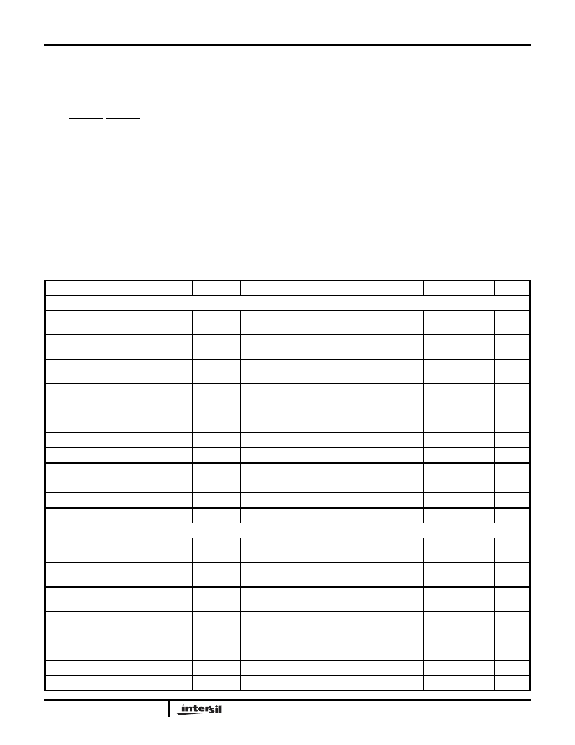
Electrical Specifications
V
DD
= 12V, C
VG
= 0.01
μ
F, C
TIM
= 0.1
μ
F, R
SENSE
= 0.1
, C
BULK
= 220
μ
F, ESR = 0.5
,
T
A
= T
J
= 0°C to 70°C, Unless Otherwise Specified
PARAMETER
SYMBOL
TEST CONDITIONS
MIN
TYP
MAX
UNITS
12V CONTROL SECTION
Current Limit Threshold Voltage
(Voltage Across Sense Resistor)
V
IL12V
V
IL12V
R
ILIM
=10k
R
ILIM
= 5k
92
47
100
53
108
59
mV
mV
3X Current Limit Threshold Voltage
(Voltage Across Sense Resistor)
3XV
iL12V
3XV
IL12V
R
ILIM
=10k
R
ILIM
= 5k
250
100
300
165
350
210
mV
mV
±
20% Current Limit Response Time
(Current within 20% of Regulated Value)
20%iLrt
200% Current Overload, R
ILIM
= 10k
,
R
SHORT
= 6.0
-
2
-
μ
s
±
10% Current Limit Response Time
(Current within 10% of Regulated Value)
10%iLrt
200% Current Overload, R
ILIM
= 10k
,
R
SHORT
= 6.0
-
4
-
μ
s
±
1% Current Limit Response Time
(Current within 1% of Regulated Value)
1%iLrt
200% Current Overload, R
ILIM
= 10k
,
R
SHORT
= 6.0
-
10
-
μ
s
Response Time To Dead Short
RT
SHORT
C
12VG
= 0.01
μ
F
-
500
1000
ns
Gate Turn-On Time
t
ON12V
C
12VG
= 0.01
μ
F
-
12
-
ms
Gate Turn-On Current
I
ON12V
C
12VG
= 0.01
μ
F
8
10
12
μ
A
3X Gate Discharge Current
3XdisI
12VG = 18V
0.5
0.75
-
A
12V Undervoltage Threshold
12V
VUV
10.5
10.8
11.0
V
Qpumped 12VG Voltage
V12VG
C
PUMP
= 0.1
μ
F
16.8
17.3
17.9
V
3.3V/5V CONTROL SECTION
Current Limit Threshold Voltage
(Voltage Across Sense Resistor)
V
IL5V
R
ILIM
=10k
R
ILIM
= 5k
92
47
100
53
108
59
mV
mV
3X Current Limit Threshold Voltage
(Voltage Across Sense Resistor)
3XV
IL5V
R
ILIM
=10k
R
ILIM
= 5k
250
100
300
155
350
210
mV
mV
±
20% Current Limit Response Time
(Current within 20% of regulated value)
200% Current Overload, R
ILIM
= 10k
,
R
SHORT
= 2.5
-
2
-
μ
s
±
10% Current Limit Response Time
(Current within 10% of Regulated Value)
200% Current Overload, R
ILIM
= 10k
,
R
SHORT
= 2.5
-
4
-
μ
s
±
1% Current Limit Response Time
(Current within 1% of Regulated Value)
200% Current Overload, R
ILIM
= 10k
,
R
SHORT
= 2.5
-
10
-
μ
s
Response Time To Dead Short
RT
SHORT
C
VG
= 0.01
μ
F
-
500
800
ns
Gate Turn-On Time
t
ON5V
C
VG
= 0.01
μ
F
-
5
-
ms
HIP1012A
相關(guān)PDF資料 |
PDF描述 |
|---|---|
| HIP1012A | Dual Power Distribution Controller(雙電源分配控制器) |
| HIP1020CK-T | nullSingle, Double or Triple-Output Hot Plug Controller |
| HIP2030 | 30V MCT/IGBT Gate Driver(MOS可控硅晶體管/絕緣柵雙極晶體管門驅(qū)動器) |
| HIP2100IB | 100V/2A Peak, Low Cost, High Frequency Half Bridge Driver |
| HIP5015EVAL2 | () |
相關(guān)代理商/技術(shù)參數(shù) |
參數(shù)描述 |
|---|---|
| HIP1012A | 制造商:INTERSIL 制造商全稱:Intersil Corporation 功能描述:Dual Power Distribution Controller |
| HIP1012A_04 | 制造商:INTERSIL 制造商全稱:Intersil Corporation 功能描述:Dual Power Distribution Controller |
| HIP1012ACB | 功能描述:IC CTRLRL HOT PLUG DUAL 14-SOIC RoHS:否 類別:集成電路 (IC) >> PMIC - 熱交換 系列:- 產(chǎn)品培訓(xùn)模塊:Obsolescence Mitigation Program 標(biāo)準(zhǔn)包裝:100 系列:- 類型:熱插拔開關(guān) 應(yīng)用:通用 內(nèi)部開關(guān):是 電流限制:可調(diào) 電源電壓:9 V ~ 13.2 V 工作溫度:-40°C ~ 150°C 安裝類型:表面貼裝 封裝/外殼:10-WFDFN 裸露焊盤 供應(yīng)商設(shè)備封裝:10-TDFN-EP(3x3) 包裝:管件 |
| HIP1012ACB-T | 功能描述:IC CTRLRL HOT PLUG DUAL 14-SOIC RoHS:否 類別:集成電路 (IC) >> PMIC - 熱交換 系列:- 產(chǎn)品培訓(xùn)模塊:Obsolescence Mitigation Program 標(biāo)準(zhǔn)包裝:100 系列:- 類型:熱插拔開關(guān) 應(yīng)用:通用 內(nèi)部開關(guān):是 電流限制:可調(diào) 電源電壓:9 V ~ 13.2 V 工作溫度:-40°C ~ 150°C 安裝類型:表面貼裝 封裝/外殼:10-WFDFN 裸露焊盤 供應(yīng)商設(shè)備封裝:10-TDFN-EP(3x3) 包裝:管件 |
| HIP1012ACBTS2490 | 制造商:INTERSIL 功能描述:New |
發(fā)布緊急采購,3分鐘左右您將得到回復(fù)。