- 您現(xiàn)在的位置:買賣IC網(wǎng) > PDF目錄385355 > HC5549 (Intersil Corporation) Low Power SLIC with Battery Switch(用戶線接口電路) PDF資料下載
參數(shù)資料
| 型號(hào): | HC5549 |
| 廠商: | Intersil Corporation |
| 英文描述: | Low Power SLIC with Battery Switch(用戶線接口電路) |
| 中文描述: | 低功耗用戶接口與電池開關(guān)(用戶線接口電路) |
| 文件頁數(shù): | 5/13頁 |
| 文件大小: | 125K |
| 代理商: | HC5549 |

4-5
Design Equations
Loop Supervision Thresholds
SWITCH HOOK DETECT
The switch hook detect threshold is set by a single external
resistor, R
SH
. Equation 1 is used to calculate the value of R
SH
.
The term I
SH
is the desired DC loop current threshold. The
loop current threshold programming range is from 5mA to
15mA.
GROUND KEY DETECT
The ground key detector senses a DC current imbalance
between the Tip and Ring terminals when the ring terminal is
connected to ground. The ground key detect threshold is not
externally programmable and is internally fixed to 12mA
regardless of the switch hook threshold.
RING TRIP DETECT
The ring trip detect threshold is set by a single external
resistor, R
RT
. I
RT
should be set between the peak ringing
current and the peak off hook current while still ringing.
The capacitor C
RT
, in parallel with R
RT
, will set the ring trip
response time.
Loop Current Limit
The loop current limit of the device is programmed by the
external resistor R
IL
. The value of R
IL
can be calculated
using Equation 3.
LIM
The term I
LIM
is the desired loop current limit. The loop
current limit programming range is from 15mA to 45mA.
Impedance Matching
The impedance of the device is programmed with the
external component R
S
. R
S
is the gain setting resistor for
the feedback amplifier that provides impedance matching. If
complex impedance matching is required, then a complex
network can be substituted for R
S
.
RESISTIVE IMPEDANCE SYNTHESIS
The source impedance of the device, Z
O
, can be calculated
in Equation 4.
The required impedance is defined by the terminating
impedance and protection resistors as shown in Equation 5.
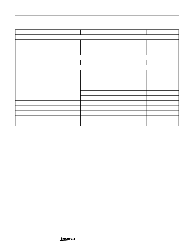
ON HOOK POWER DISSIPATION
Forward or Reverse
BSEL = 0
-
44
60
mW
Forward or Reverse
BSEL = 1
-
90
150
mW
Low Power Standby
BSEL = 1
-
37
60
mW
OFF HOOK POWER DISSIPATION
Forward or Reverse
BSEL = 0
-
290
310
mW
POWER SUPPLY REJECTION RATIO
V
CC
to 2-Wire
f = 300Hz
-
40
-
dB
f = 1kHz
-
35
-
dB
f = 3.4kHz
-
28
-
dB
V
CC
to 4-Wire
f = 300Hz
-
45
-
dB
f = 1kHz
-
43
-
dB
f = 3.4kHz
-
33
-
dB
V
BL
to 2-Wire
300Hz
≤
f
≤
3.4kHz
-
30
-
dB
V
BL
to 4-Wire
300Hz
≤
f
≤
3.4kHz
-
35
-
dB
V
BH
to 2-Wire
300Hz
≤
f
≤
3.4kHz
-
33
-
dB
V
BH
to 4-Wire
300Hz
≤
f
≤
1kHz
-
40
-
dB
1kHz
<
f
≤
3.4kHz
-
45
-
dB
Electrical Specifications
Unless Otherwise Specified, T
A
= -40
o
C to 85
o
C, V
BL
= -24V, V
BH
= -48V, V
CC
= +5V, AGND = BGND = 0V, loop
current limit = 25mA. All AC Parameters are specified at 600
2-wire terminating impedance over the frequency
band of 300Hz to 3.4kHz. Protection resistors = 0
.
(Continued)
PARAMETER
TEST CONDITIONS
MIN
TYP
MAX
UNITS
R
SH
600 I
SH
=
(EQ. 1)
R
RT
1800 I
RT
=
(EQ. 2)
R
IL
------------
=
(EQ. 3)
R
S
400 Z
O
)
=
(EQ. 4)
HC5549
相關(guān)PDF資料 |
PDF描述 |
|---|---|
| HC573 | Octal 3-State Noninverting Transparent Latch(High-Performance Silicon-Gate CMOS) |
| HC595 | 8-Bit Serial-Input/Serial or Parallel-Output Shift Register with Latched 3-State Outputs |
| HC652 | EPROM IC; Memory Size:128Kbit; Memory Configuration:16K x 8; Access Time, Tacc:250ns; Package/Case:28-DIP; EPROM Type:Parallel UV Erasable; Supply Voltage Nom, Vcc:5V; Mounting Type:Through Hole; Voltage Rating:5V |
| HC74 | T-NPN-SI PWR AMP |
| HCA10008 | Darlington Bipolar Transistor; Package/Case:TO-3; Mounting Type:Through Hole; Current Rating:50A; Voltage Rating:120V |
相關(guān)代理商/技術(shù)參數(shù) |
參數(shù)描述 |
|---|---|
| HC5549_04 | 制造商:INTERSIL 制造商全稱:Intersil Corporation 功能描述:Low Power SLIC with Battery Switch |
| HC5549CM | 制造商:Rochester Electronics LLC 功能描述: |
| HC5549CMZ | 制造商:Intersil Corporation 功能描述:SLIC 1CH 59DB 45MA 5V 28PLCC - Rail/Tube |
| HC5549IM | 制造商:INTERSIL 制造商全稱:Intersil Corporation 功能描述:Low Power SLIC with Battery Switch |
| HC5552 | 制造商:未知廠家 制造商全稱:未知廠家 功能描述:Telecommunication IC |
發(fā)布緊急采購(gòu),3分鐘左右您將得到回復(fù)。