- 您現(xiàn)在的位置:買(mǎi)賣(mài)IC網(wǎng) > PDF目錄97865 > DS18S20Z/T&R (MAXIM INTEGRATED PRODUCTS INC) DIGITAL TEMP SENSOR-SERIAL, 9BIT(s), 0.50Cel, RECTANGULAR, SURFACE MOUNT PDF資料下載
參數(shù)資料
| 型號(hào): | DS18S20Z/T&R |
| 廠商: | MAXIM INTEGRATED PRODUCTS INC |
| 元件分類(lèi): | Switch/Digital Output Temperature Sensor |
| 英文描述: | DIGITAL TEMP SENSOR-SERIAL, 9BIT(s), 0.50Cel, RECTANGULAR, SURFACE MOUNT |
| 封裝: | SOP-8 |
| 文件頁(yè)數(shù): | 17/23頁(yè) |
| 文件大小: | 252K |
| 代理商: | DS18S20Z/T&R |
第1頁(yè)第2頁(yè)第3頁(yè)第4頁(yè)第5頁(yè)第6頁(yè)第7頁(yè)第8頁(yè)第9頁(yè)第10頁(yè)第11頁(yè)第12頁(yè)第13頁(yè)第14頁(yè)第15頁(yè)第16頁(yè)當(dāng)前第17頁(yè)第18頁(yè)第19頁(yè)第20頁(yè)第21頁(yè)第22頁(yè)第23頁(yè)
DS18S20
3 of 23
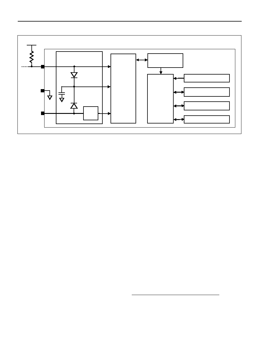
Figure 1. DS18S20 Block Diagram
OPERATION—MEASURING TEMPERATURE
The core functionality of the DS18S20 is its direct-to-digital temperature sensor. The temperature sensor
output has 9-bit resolution, which corresponds to 0.5
°C steps. The DS18S20 powers-up in a low-power
idle state; to initiate a temperature measurement and A-to-D conversion, the master must issue a Convert
T [44h] command. Following the conversion, the resulting thermal data is stored in the 2-byte
temperature register in the scratchpad memory and the DS18S20 returns to its idle state. If the DS18S20
is powered by an external supply, the master can issue “read-time slots” (see the 1-Wire Bus System
section) after the Convert T command and the DS18S20 will respond by transmitting 0 while the
temperature conversion is in progress and 1 when the conversion is done. If the DS18S20 is powered with
parasite power, this notification technique cannot be used since the bus must be pulled high by a strong
pullup during the entire temperature conversion. The bus requirements for parasite power are explained in
detail in the Powering the DS18S20 section.
The DS18S20 output data is calibrated in degrees centigrade; for Fahrenheit applications, a lookup table
or conversion routine must be used. The temperature data is stored as a 16-bit sign-extended two’s
complement number in the temperature register (see Figure 2). The sign bits (S) indicate if the
temperature is positive or negative: for positive numbers S = 0 and for negative numbers S = 1. Table 1
gives examples of digital output data and the corresponding temperature reading.
Resolutions greater than 9 bits can be calculated using the data from the temperature, COUNT REMAIN
and COUNT PER °C registers in the scratchpad. Note that the COUNT PER °C register is hard-wired to
16 (10h). After reading the scratchpad, the TEMP_READ value is obtained by truncating the 0.5
°C bit
(bit 0) from the temperature data (see Figure 2). The extended resolution temperature can then be
calculated using the following equation:
C
PER
COUNT
REMAIN
COUNT
C
PER
COUNT
READ
TEMP
E
TEMPERATUR
_
25
.
0
_
+
=
VPU
4.7k
POWER-
SUPPLY
SENSE
64-BIT ROM
AND
1-Wire PORT
DQ
VDD
INTERNAL VDD
CPP
PARASITE POWER
CIRCUIT
MEMORY CONTROL
LOGIC
SCRATCHPAD
8-BIT CRC GENERATOR
TEMPERATURE SENSOR
ALARM HIGH TRIGGER (TH)
REGISTER (EEPROM)
ALARM LOW TRIGGER (TL)
REGISTER (EEPROM)
GND
DS18S20
相關(guān)PDF資料 |
PDF描述 |
|---|---|
| DS1963L-F5 | SPECIALTY MEMORY CIRCUIT, MEDB2 |
| DS1963S | SPECIALTY MEMORY CIRCUIT, MEDB2 |
| DS1985-F3 | 2K X 8 EEPROM 3V, RDB2 |
| DS1986-F3 | 64K X 1 OTPROM, MEDB2 |
| DS1986-F5 | 64K X 1 OTPROM, MADB2 |
相關(guān)代理商/技術(shù)參數(shù) |
參數(shù)描述 |
|---|---|
| DS18VN6LPQ | 制造商:Banner Engineering 功能描述:SENSOR, PHOTOELECTRIC, DS18VN6LPQ PICO QP NPN POL RET |
| DS18VP6FF50Q8 | 制造商:Banner Engineering 功能描述:DS18VP6FF50Q8 EURO QD PNP 50MM FIXED FIELD |
| DS18VP6LP-29537 | 制造商:Banner Engineering 功能描述:DS18 Series: Polarized Retro, Range: 3.5 m, Input: 10-30V dc, Output: Complement |
| DS18VP6LPQ8 | 制造商:Banner Engineering 功能描述:SENSOR, PHOTOELECTRIC, DS18VP6LPQ8 EURO QD PNP POL RETRO |
| DS1904 | 制造商:MAXIM 制造商全稱:Maxim Integrated Products 功能描述:Real-Time Clock/calendar in binary format RTC iButton Over 10 years of operation |
發(fā)布緊急采購(gòu),3分鐘左右您將得到回復(fù)。