- 您現(xiàn)在的位置:買賣IC網(wǎng) > PDF目錄369534 > BTS650PE3180A Transient Voltage Suppressor Diodes PDF資料下載
參數(shù)資料
| 型號(hào): | BTS650PE3180A |
| 元件分類: | TVS-瞬態(tài)抑制二極管 |
| 英文描述: | Transient Voltage Suppressor Diodes |
| 中文描述: | 單外設(shè)驅(qū)動(dòng) |
| 文件頁數(shù): | 2/16頁 |
| 文件大小: | 236K |
| 代理商: | BTS650PE3180A |
Data Sheet BTS650P
Infineon Technologies AG
Page 2
2000-Mar-24
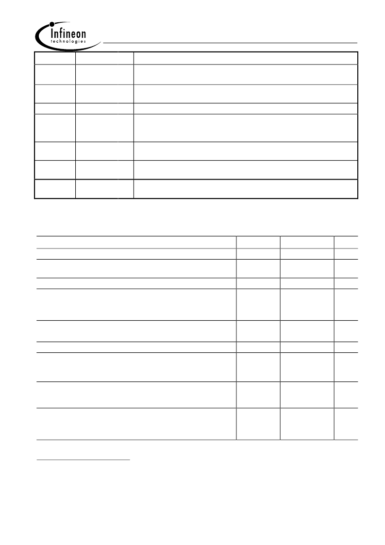
Pin
Symbol
Function
1
OUT
O
Output to the load. The pins
1,2,6 and 7 must be shorted with each other
especially in high current applications!
3
)
2
OUT
O
Output to the load. The pins
1,2,6 and 7 must be shorted with each other
especially in high current applications!
3)
3
IN
I
Input, activates the power switch in case of short to ground
4
Vbb
+
Positive power supply voltage, the tab is electrically connected to this pin.
In high current applications the tab should be used for the V
bb
connection
instead of this pin
4
)
.
Diagnostic feedback providing a sense current proportional to the load
current; zero current on failure (see Truth Table on page 7)
5
IS
S
6
OUT
O
Output to the load. The pins
1,2,6 and 7 must be shorted with each other
especially in high current applications!
3)
7
OUT
O
Output to the load. The pins
1,2,6 and 7 must be shorted with each other
especially in high current applications!
3)
Maximum Ratings
at
T
j
= 25 °C unless otherwise specified
Parameter
Supply voltage
(overvoltage protection see page 4)
Supply voltage for short circuit protection,
T
j,start
=-40 ...+150°C:
(see diagram on page 10)
Load current (short circuit current, see page 5)
Load dump protection
V
LoadDump
=
V
A
+
V
s
,
V
A
=
13.5
V
R
I
IN,
IS
= open or grounded
Operating temperature range
Storage temperature range
Power dissipation (DC), T
C
25 °C
Inductive load switch-off energy dissipation, single pulse
V
bb
=
12V,
T
j,start
=
150°C,
T
C
=
150°C const.,
I
L
=
20
A, Z
L
=
7.5
mH, 0
,
see diagrams on page 10
Electrostatic discharge capability (ESD)
Human Body Model acc. MIL-STD883D, method 3015.7 and ESD
assn. std. S5.1-1993, C = 100 pF, R = 1.5 k
Current through input pin (DC)
Current through current sense status pin (DC)
see internal circuit diagrams on page 7 and 8
Symbol
V
bb
V
bb
Values
Unit
42
34
V
V
I
L
self-limited
A
5
)
=
2
,
R
L
=
0.54
,
t
d
=
200
ms,
V
Load dump
6
)
75
V
T
j
T
stg
P
tot
-40 ...+150
-55 ...+150
°C
170
W
E
AS
1.5
J
V
ESD
4
kV
I
IN
I
IS
+15
, -250
+15
, -250
mA
3
)
Not shorting all outputs will considerably increase the on-state resistance, reduce the peak current capability
and decrease the current sense accuracy
4
)
Otherwise add up to 0.7 m (depending on used length of the pin) to the R
ON
if the pin is used instead of
the tab.
5
)
R
I
= internal resistance of the load dump test pulse generator.
6
)
V
Load dump
is setup without the DUT connected to the generator per ISO 7637-1 and DIN 40839.
相關(guān)PDF資料 |
PDF描述 |
|---|---|
| BTS650PE3230 | Transient Voltage Suppressor Diodes |
| BTS6510B | Transient Voltage Suppressor Diodes |
| BTS660-P | Transient Voltage Suppressor Diodes |
| BTS711-L1 | Transient Voltage Suppressor Diodes |
| BTS711L1Q67060-S7000-A2 | Transient Voltage Suppressor Diodes |
相關(guān)代理商/技術(shù)參數(shù) |
參數(shù)描述 |
|---|---|
| BTS650PE3180ANT | 制造商:Infineon Technologies AG 功能描述:Power Switch Hi Side 13.6A 8-Pin(7+Tab) TO-220 SMD T/R |
| BTS650PE3180ANTMA1 | 制造商:Infineon Technologies AG 功能描述:IC SWITCH PWR HISIDE TO220-7 SMD |
| BTS650PE3180AT | 制造商:Infineon Technologies AG 功能描述:Power Switch Hi Side 13.6A 8-Pin(7+Tab) TO-220 SMD T/R |
| BTS650PE3230 | 制造商:未知廠家 制造商全稱:未知廠家 功能描述:Single Peripheral Driver |
| BTS6510 | 制造商:INFINEON 制造商全稱:Infineon Technologies AG 功能描述:Smart Highside High Current Power Switch |
發(fā)布緊急采購,3分鐘左右您將得到回復(fù)。