- 您現(xiàn)在的位置:買賣IC網(wǎng) > PDF目錄375361 > ASDP-21365BBC-1AA (ANALOG DEVICES INC) SHARC Processor PDF資料下載
參數(shù)資料
| 型號(hào): | ASDP-21365BBC-1AA |
| 廠商: | ANALOG DEVICES INC |
| 元件分類: | 數(shù)字信號(hào)處理 |
| 英文描述: | SHARC Processor |
| 中文描述: | 16-BIT, 55.55 MHz, OTHER DSP, PBGA136 |
| 封裝: | MO-205AE, BGA-136 |
| 文件頁數(shù): | 47/52頁 |
| 文件大?。?/td> | 1320K |
| 代理商: | ASDP-21365BBC-1AA |
第1頁第2頁第3頁第4頁第5頁第6頁第7頁第8頁第9頁第10頁第11頁第12頁第13頁第14頁第15頁第16頁第17頁第18頁第19頁第20頁第21頁第22頁第23頁第24頁第25頁第26頁第27頁第28頁第29頁第30頁第31頁第32頁第33頁第34頁第35頁第36頁第37頁第38頁第39頁第40頁第41頁第42頁第43頁第44頁第45頁第46頁當(dāng)前第47頁第48頁第49頁第50頁第51頁第52頁
ADSP-21362/ADSP-21363/ADSP-21364/ADSP-21365/ADSP-21366
Rev. A
|
Page 47 of 52
|
December 2006
THERMAL CHARACTERISTICS
The ADSP-2136x processor is rated for performance over the
temperature range specified in Operating Conditions
on Page 16
.
Table 41
and
Table 42
airflow measurements comply with
JEDEC standards JESD51-2 and JESD51-6 and the junction-to-
board measurement complies with JESD51-8. Test board and
thermal via design comply with JEDEC standards JESD51-9
(BGA). The junction-to-case measurement complies with MIL-
STD-883. All measurements use a 2S2P JEDEC test board.
Industrial applications using the BGA package require thermal
vias, to an embedded ground plane, in the PCB. Refer to JEDEC
standard JESD51-9 for printed circuit board thermal ball land
and thermal via design information.
To determine the junction temperature of the device while on
the application PCB, use:
where:
T
J
= junction temperature (
°
C)
T
T
= case temperature (
°
C) measured at the top center of the
package
Ψ
JT
= junction-to-top (of package) characterization parameter
is the typical value from
Table 41
.
P
D
= power dissipation (see EE Note No. EE-277 for more
information).
Values of
θ
JA
are provided for package comparison and PCB
design considerations.
Values of
θ
JC
are provided for package comparison and PCB
design considerations when an external heat sink is required.
Note that the thermal characteristics values provided in
Table 41
and
Table 42
are modeled values.
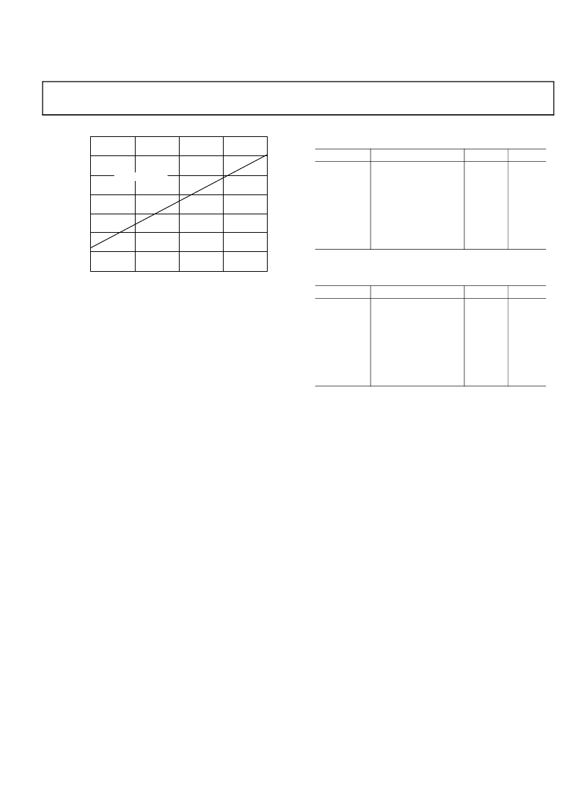
Figure 42. Typical Output Delay or Hold vs. Load Capacitance
(at Ambient Temperature)
LOAD CAPACITANCE (pF)
0
200
50
100
150
10
8
O
6
0
4
2
-
2
Y = 0.0488x
-
1.5923
-
4
T
J
T
T
Ψ
JT
P
D
×
(
)
+
=
Table 41. Thermal Characteristics for BGA (No thermal vias
in PCB)
Parameter
θ
JA
θ
JMA
θ
JMA
θ
JC
Ψ
JT
Ψ
JMT
Ψ
JMT
Condition
Airflow = 0 m/s
Airflow = 1 m/s
Airflow = 2 m/s
Typical
25.40
21.90
20.90
5.07
0.140
0.330
0.410
Unit
°C/W
°C/W
°C/W
°C/W
°C/W
°C/W
°C/W
Airflow = 0 m/s
Airflow = 1 m/s
Airflow = 2 m/s
Table 42. Thermal Characteristics for BGA (Thermal vias in
PCB)
Parameter
θ
JA
θ
JMA
θ
JMA
θ
JC
Ψ
JT
Ψ
JMT
Ψ
JMT
Condition
Airflow = 0 m/s
Airflow = 1 m/s
Airflow = 2 m/s
Typical
23.40
20.00
19.20
5.00
0.130
0.300
0.360
Unit
°C/W
°C/W
°C/W
°C/W
°C/W
°C/W
°C/W
Airflow = 0 m/s
Airflow = 1 m/s
Airflow = 2 m/s
相關(guān)PDF資料 |
PDF描述 |
|---|---|
| ASDP-21365BBCZ-1AA | SHARC Processor |
| ASDP-21365KBC-1AA | SHARC Processor |
| ASDP-21365KBCZ-1AA | SHARC Processor |
| ASDP-21365WBBCZ-1A | SHARC Processor |
| ASG509A | CMOS 4/8 CHAANNEL ANALOG MULTIPLEXERS |
相關(guān)代理商/技術(shù)參數(shù) |
參數(shù)描述 |
|---|---|
| ASDP-21365BBCZ-1AA | 制造商:AD 制造商全稱:Analog Devices 功能描述:SHARC Processor |
| ASDP-21365KBC-1AA | 制造商:AD 制造商全稱:Analog Devices 功能描述:SHARC Processor |
| ASDP-21365KBCZ-1AA | 制造商:AD 制造商全稱:Analog Devices 功能描述:SHARC Processor |
| ASDP-21365WBBCZ-1A | 制造商:AD 制造商全稱:Analog Devices 功能描述:SHARC Processor |
| ASD-PL2F | 制造商:GAMEWELL-FCI 制造商全稱:GAMEWELL-FCI 功能描述:Analog, addressable photoelectronic smoke sensor |
發(fā)布緊急采購,3分鐘左右您將得到回復(fù)。