- 您現(xiàn)在的位置:買賣IC網(wǎng) > PDF目錄373980 > ADE7754 (Analog Devices, Inc.) ADE7754 PDF資料下載
參數(shù)資料
| 型號(hào): | ADE7754 |
| 廠商: | Analog Devices, Inc. |
| 英文描述: | ADE7754 |
| 中文描述: | ADE7754 |
| 文件頁數(shù): | 22/44頁 |
| 文件大?。?/td> | 630K |
| 代理商: | ADE7754 |
第1頁第2頁第3頁第4頁第5頁第6頁第7頁第8頁第9頁第10頁第11頁第12頁第13頁第14頁第15頁第16頁第17頁第18頁第19頁第20頁第21頁當(dāng)前第22頁第23頁第24頁第25頁第26頁第27頁第28頁第29頁第30頁第31頁第32頁第33頁第34頁第35頁第36頁第37頁第38頁第39頁第40頁第41頁第42頁第43頁第44頁
REV. PrG 01/03
PRELIMINARY TECHNICAL DATA
ADE7754
–
22
–
ENERGY CALCULATION
As stated earlier, power is defined as the rate of energy flow.
This relationship can be expressed mathematically as
Equation 7.
P =dE
dt
Where P = Power and E = Energy.
Conversely Energy is given as the integral of Power.
The ADE7754 achieves the integration of the Active Power
signal by continuously accumulating the Active Power signal
in an internal non-readable 54-bit Energy register. The
Active Energy register (AENERGY[23:0]) represents the
upper 24 bits of this internal register. This discrete time
accumulation or summation is equivalent to integration in
continuous time. Equation 9 below expresses the relationship
(7)
E= Pdt
(8)
E=
dt
Lim
p(t)
0
=
∫
∑
=
×
∞
p nT
(
T
)
(9)
Where n is the discrete time sample number and T is the
sample period.
The discrete time sample period (T) for the accumulation
register in the ADE7754 is 0.4μs (4/10MHz). As well as
calculating the Energy, this integration removes any sinusoi-
dal component which may be in the Active Power signal.
Figure 26 shows a graphical representation of this discrete
time integration or accumulation. The Active Power signal
is continuously added to the internal Energy register. This
addition is a signed addition, therefore negative energy will
be subtracted from the Active Energy contents.
53
0
+
+
Σ
TOTAL ACTIVE POWER
00000h
26667h
time (nT)
T
TOTAL ACTIVE POWER ARE
ACCUMULATED (INTEGRATED) IN
THE ACTIVE ENERGY REGISTER
Active Power
Signal - P
T
53
0
AENERGY[23:0]
WDIV
23
0
Figure 25 –ADE7754 Active Energy calculation
The 54-bit of the internal Energy register are divided by
WDIV. If the value in the WDIV register is equal to 0 then
the internal Active Energy register is divided by 1. WDIV is
an 8-bit unsigned register. The upper 24-bit of the result of
the division are then available in the 24-bit Active Energy
register. The AENERGY and RAENERGY registers read
the same internal Active energy register. They differ by the
the state in which they are leaving the internal Active energy
register after a read. Two operations are held when reading
the RAENERGY register: Read and reset to zero the internal
Active Energy register. Only one operation is held when
reading the AENERGY register: read the internal Active
Energy register.
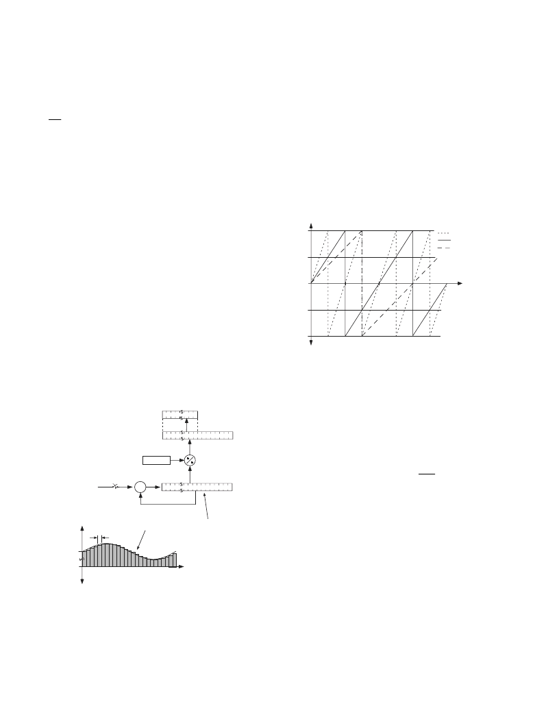
Figure 26 shows the energy accumulation for full scale
signals (sinusoidal) on the analog inputs. The three displayed
curves, illustrate the minimum time it takes the energy
register to roll-over, when the individual Watt Gain registers
contents are all equal to 3FFh, 000h and 800h. The Watt
Gain registers are used to carry out a power calibration in the
ADE7754. As shown, the fastest integration time occurs
when the Watt Gain registers are set to maximum full scale,
i.e., 3FFh.
00,0000h
7F,FFFFh
80,0000h
3F,FFFFh
40,0000h
AENERGY[23:0]
Time
(seconds)
AWG = BWG = CWG = 3FFh
AWG = BWG = CWG = 000h
AWG = BWG = CWG = 800h
88
176
264
44
132
220
Figure 26 –Energy register roll-over time for full-scale
power (Minimum & Maximum Power Gain)
Note that the Active Energy register contents roll over to full-
scale negative (80,0000h) and continue increasing in value
when the power or energy flow is positive -See Figure 26.
Conversely if the power is negative the energy register would
under flow to full scale positive (7F,FFFFh) and continue
decreasing in value.
By using the Interrupt Enable register, the ADE7754 can be
configured to issue an interrupt (
IRQ
) when the Active
Energy register is half full (positive or negative).
相關(guān)PDF資料 |
PDF描述 |
|---|---|
| ADE7754AR | ADE7754 |
| ADE7754ARRL | ADE7754 |
| ADE7755AN-REF | Energy Metering IC with Pulse Output |
| ADE7755ARSRL | Energy Metering IC with Pulse Output |
| ADE7755 | Energy Metering IC with Pulse Output |
相關(guān)代理商/技術(shù)參數(shù) |
參數(shù)描述 |
|---|---|
| ADE7754AR | 制造商:Analog Devices 功能描述:Energy Measurement 24-Pin SOIC W 制造商:Rochester Electronics LLC 功能描述:THREE PHASE ENERGY METER IC W/WATT & VA - Bulk 制造商:Analog Devices 功能描述:IC ENERGY METER |
| ADE7754ARRL | 制造商:Analog Devices 功能描述:Energy Measurement 24-Pin SOIC W T/R 制造商:Rochester Electronics LLC 功能描述:THREE PHASE ENERGY METER IC W/WATT & VA - Bulk |
| ADE7754ARZ | 功能描述:IC ENERGY METERING 3PHASE 24SOIC RoHS:是 類別:集成電路 (IC) >> PMIC - 能量測量 系列:- 產(chǎn)品培訓(xùn)模塊:Lead (SnPb) Finish for COTS Obsolescence Mitigation Program 標(biāo)準(zhǔn)包裝:2,500 系列:* |
| ADE7754ARZRL | 功能描述:IC ENERGY METERING 3PHASE 24SOIC RoHS:是 類別:集成電路 (IC) >> PMIC - 能量測量 系列:- 產(chǎn)品培訓(xùn)模塊:Lead (SnPb) Finish for COTS Obsolescence Mitigation Program 標(biāo)準(zhǔn)包裝:2,500 系列:* |
| ADE7755 | 制造商:AD 制造商全稱:Analog Devices 功能描述:Energy Metering IC with Pulse Output |
發(fā)布緊急采購,3分鐘左右您將得到回復(fù)。