- 您現(xiàn)在的位置:買賣IC網(wǎng) > PDF目錄375230 > AD1843JST (ANALOG DEVICES INC) Serial-Port 16-Bit SoundComm Codec PDF資料下載
參數(shù)資料
| 型號: | AD1843JST |
| 廠商: | ANALOG DEVICES INC |
| 元件分類: | 消費家電 |
| 英文描述: | Serial-Port 16-Bit SoundComm Codec |
| 中文描述: | SPECIALTY CONSUMER CIRCUIT, PQFP100 |
| 封裝: | PLASTIC, TQFP-100 |
| 文件頁數(shù): | 15/64頁 |
| 文件大小: | 848K |
| 代理商: | AD1843JST |
第1頁第2頁第3頁第4頁第5頁第6頁第7頁第8頁第9頁第10頁第11頁第12頁第13頁第14頁當前第15頁第16頁第17頁第18頁第19頁第20頁第21頁第22頁第23頁第24頁第25頁第26頁第27頁第28頁第29頁第30頁第31頁第32頁第33頁第34頁第35頁第36頁第37頁第38頁第39頁第40頁第41頁第42頁第43頁第44頁第45頁第46頁第47頁第48頁第49頁第50頁第51頁第52頁第53頁第54頁第55頁第56頁第57頁第58頁第59頁第60頁第61頁第62頁第63頁第64頁
AD1843
REV. 0
–15–
lock loops, which can be arbitrarily assigned to the conversion
resources. The lock range of these digital PLLs is 4 kHz to
54 kHz, which is the same range supported by the register-
controlled clock generators.
If a SYNC input stops after its associated phase lock loop has
had a chance to initially lock, the AD1843 will continue to gen-
erate a sample clock (as well as BIT clock and CONV clock)
very similar to the initial frequency, but off by at most
±
1%.
The three SYNC inputs feed three on-chip Digital Phase Lock
Loops (DPLLs) which utilize a first-order loop filter with a
20 Hz corner frequency. Jitter frequencies above 20Hz are
attenuated, and jitter frequencies below 20 Hz are interpreted as
time base drift, and are tracked. The DPLL provides 12dB per
octave of jitter rejection. The DPLLs have been designed to tol-
erate at least 2% Unit Interval (UI) of SYNC clock jitter. The
DPLLs are critically damped at all input frequencies.
Power Management
The AD1843 SoundComm codec has extensive power manage-
ment capabilities. Hardware power down is performed using the
PWRDWN
pin. Software power management is programmed us-
ing Control Register Address 27 and 28. Several elements of the
AD1843 can be powered down on a selective basis. These blocks
include: the DAC2 to DAC1 analog mixer; the entire DAC1 con-
version channel; the entire DAC2 conversion channel; the analog
half of the ADC, DAC1 and DAC2; the headphone driver; the en-
tire analog mixer; the right ADC channel; the left ADC channel; all
four conversion channels; clock generator 1; clock generator 2;
clock generator 3; conversion clock outputs 1 through 3; bit clock
outputs 1 through 3; and the nominal 24.576 MHz clock output.
Refer to the descriptions of Control Register Address 27 and 28 for
further information.
For proper operation, the AD1843 must be calibrated following
power-up. This initial calibration occurs automatically without any
user intervention or programming. Subsequent to this initial
power-up autocalibration, there is no requirement to recalibrate the
SoundComm codec following software power-down sequences.
The entire AD1843 or selected portions of the device may be
powered down, allowed to idle indefinitely, then powered up
and used immediately, without the need for repeated auto-
calibration. The digital information obtained during the initial
power-up calibration is retained and valid unless the
RESET
or
PWRDWN
pin is asserted, forcing a hardware reset. (If desired,
the user can specify that a calibration cycle occur when leaving
the software power-down state by setting ACEN (Control Reg-
ister Address 28, Bit 14) to ”1.”) A hardware reset or power-
down clears the calibration information, and therefore a fresh
autocalibration cycle is performed by the AD1843 following this
event. Autocalibration takes approximately 4 ms to complete.
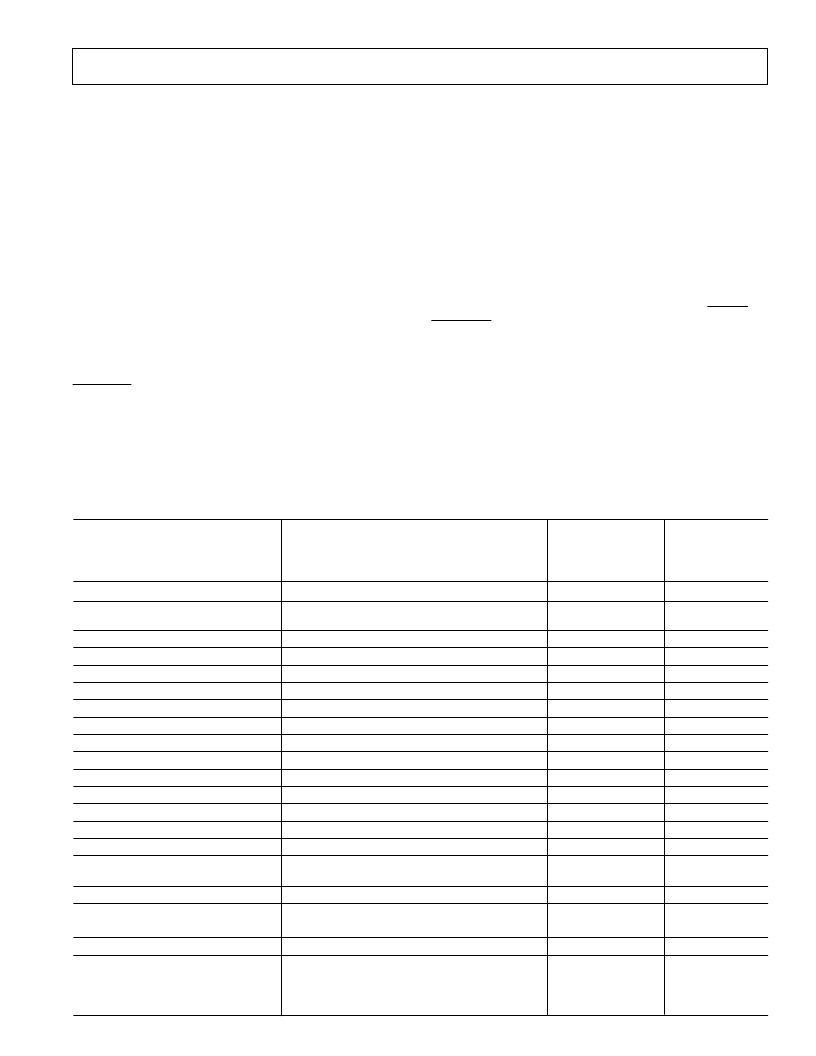
The following table provides an indication of the power savings
associated with powering-down the various resources in the
AD1843. Note that the power savings is somewhat order-
Table I. AD1843 Power-Down Savings
+5 V Digital, +5 V Analog Supplies
Total Active Operation Current: 200 mA
Average, Typical
Absolute I
DD
+
I
CC
Current
Average, Typical
Normalized
Power Savings
Software Power Down
Control Register Bit(s)
CLKOUT Output
All Bit Clocks and
All Conversion Clocks
Clock Generator 1
Clock Generator 2
Clock Generator 3
All Clock Generators
Headphone Driver
DAC2 to DAC1 Mix
Analog Input to Analog Output Mix
ADC Left Channel
ADC Right Channel
ADC Left and Right Channels
DAC2 (Left and Right Channels)
DAC1 (Left and Right Channels)
DAC2 AND DAC1 (Left and Right Chs)
ADC and DAC2 and DAC1
ENCLKO Bit = 0
ENBT3, ENBT2, ENBT1 Bits = 0
ENCV3, ENCV2, ENCV1 Bits = 0
C1EN Bit = 0
C2EN Bit = 0
C3EN Bit = 0
C1EN, C2EN, C3EN Bits = 0
HPEN Bit = 0
DDMEN Bit = 0
AAMEN Bit = 0
ADLEN Bit = 0
ADREN Bit = 0
ADLEN, ADREN Bits = 0
DA2EN Bit = 0
DA1EN Bit = 0
DA2EN, DA1EN Bits = 0
ADLEN, ADREN,
DA2EN, DA1EN Bits = 0
ANAEN Bit = 0
HPEN, DDMEN, AAMEN, ADLEN,
ADREN, DA2EN, DA1EN, ANAEN Bits = 0
8 mA
4%
2 mA
6 mA
6 mA
6 mA
20 mA
8 mA
2 mA
8 mA
8 mA
8 mA
38 mA
30 mA
24 mA
60 mA
1%
3%
3%
3%
10%
4%
1%
4%
4%
4%
17%
15%
12%
30%
108 mA
54 mA
54%
27%
Analog Channel
All Control Register 27
134 mA
67%
Converter
PDNI Bit = 1
140 mA
70%
All of the Above (Register 27 and
Clocks and PDNI)
ENCLKO, ENBT3, ENBT2, ENBT1, ENCV3,
ENCV2, ENCV1, C1EN, C2EN, C3EN, HPEN,
DDMEN, AAMEN, ADLEN, ADREN, DA2EN,
DA1EN, ANAEN Bits = 0, PDNI Bit = 1
176 mA
88%
相關(guān)PDF資料 |
PDF描述 |
|---|---|
| AD1846JP | Low Cost Parallel-Port 16-Bit SoundPort Stereo Codec |
| AD1849KP | Serial-Port 16-Bit SoundPort Stereo Codec |
| AD1851 | 16-Bit, 16×Fs PCM Audio DACs(16位,單片PCM音頻D/A轉(zhuǎn)換器) |
| AD1892JR | Integrated Digital Receiver/Rate Converter |
| AD1892JRRL | Integrated Digital Receiver/Rate Converter |
相關(guān)代理商/技術(shù)參數(shù) |
參數(shù)描述 |
|---|---|
| AD1845 | 制造商:AD 制造商全稱:Analog Devices 功能描述:Parallel-Port 16-Bit SoundPort Stereo Codec |
| AD1845JP | 制造商:Analog Devices 功能描述:Audio Codec 2ADC / 2DAC 16-Bit 68-Pin PLCC 制造商:Rochester Electronics LLC 功能描述:16 BIT AUDIO CODEC - Bulk 制造商:Analog Devices 功能描述:IC CODEC 16-BIT AUDIO |
| AD1845JP-REEL | 制造商:Analog Devices 功能描述:Audio Codec 2ADC / 2DAC 16-Bit 68-Pin PLCC T/R |
| AD1845JPZ | 制造商:Analog Devices 功能描述:Audio Codec 2ADC / 2DAC 16-Bit 68-Pin PLCC |
| AD1845JST | 制造商:Analog Devices 功能描述:Audio Codec 2ADC / 2DAC 16-Bit 100-Pin LQFP 制造商:Analog Devices 功能描述:IC CODEC 16-BIT AUDIO |
發(fā)布緊急采購,3分鐘左右您將得到回復(fù)。