- 您現(xiàn)在的位置:買賣IC網(wǎng) > PDF目錄360230 > 522923D Dual/Triple Ultra-Low-Voltage SOT23 µP Supervisory Circuits PDF資料下載
參數(shù)資料
| 型號(hào): | 522923D |
| 英文描述: | Dual/Triple Ultra-Low-Voltage SOT23 µP Supervisory Circuits |
| 中文描述: | 集成電路 |
| 文件頁(yè)數(shù): | 23/24頁(yè) |
| 文件大小: | 418K |
| 代理商: | 522923D |
第1頁(yè)第2頁(yè)第3頁(yè)第4頁(yè)第5頁(yè)第6頁(yè)第7頁(yè)第8頁(yè)第9頁(yè)第10頁(yè)第11頁(yè)第12頁(yè)第13頁(yè)第14頁(yè)第15頁(yè)第16頁(yè)第17頁(yè)第18頁(yè)第19頁(yè)第20頁(yè)第21頁(yè)第22頁(yè)當(dāng)前第23頁(yè)第24頁(yè)
23
LTC1286/LTC1298
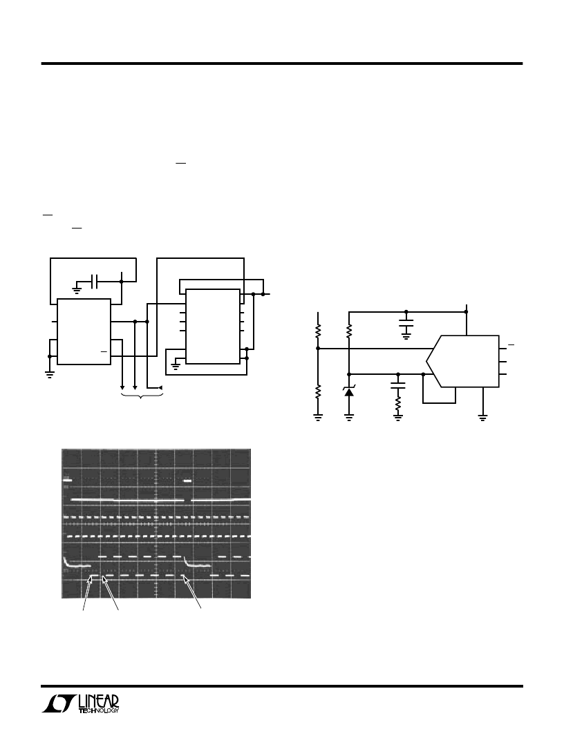
A “Quick Look” Circuit for the LTC1286
Users can get a quick look at the function and timing of the
LT1286 by using the following simple circuit (Figure 13).
V
REF
is tied to V
CC
. V
IN
is applied to the +IN input and the
–IN input is tied to the ground. CS is driven at 1/16 the
clock rate by the 74C161 and D
OUT
outputs the data. The
output data from the D
OUT
pin can be viewed on an
oscilloscope that is set up to trigger on the falling edge of
CS (Figure 14). Note the LSB data is partially clocked out
before CS goes high.
TYPICAL APPLICATIO
S
N
U
Micropower Battery Voltage Monitor
A common problem in battery systems is battery voltage
monitoring. This circuit monitors the 10 cell stack of NiCad
or NiMH batteries found in laptop computers. It draws only
67
μ
A from the 5V supply at f
SMPL
= 0.1kHz and 25
μ
A to
55
μ
A from the battery. The 12-bits of resolution of the
LTC1286 are positioned over the desired range of 8V to
16V. This is easily accomplished by using the ADC’s
differential inputs. Tying the –input to the reference gives
an ADC input span of V
REF
to 2V
REF
(2.5V to 5V). The
resistor divider then scales the input voltage for 8V to 16V.
Figure 13. “Quick Look” Circuit for the LTC1286
CLR
CLK
A
B
C
D
P
GND
V
CC
RC
QA
QB
QC
QD
T
LOAD
74C161
V
IN
TO OSCILLOSCOPE
CLOCK IN 250kHz
LTC1286/98 F13
V
CC
CLK
D
OUT
LTC1286
V
REF
+IN
–IN
GND
4.7
μ
F
5V
5V
CS
Figure 14. Scope Trace the LTC1286 “Quick Look” Circuit
Showing A/D Output 101010101010 (AAA
HEX
)
Figure 15. Micropower Battery Voltage Monitor
39k
5V
LT1004-2.5
200k
91k
3
BATTERY MONITOR
INPUT 8V TO 16V
1
μ
F
0.1
μ
F
CS
CLK
D
OUT
LTC1286
LTC1286/98 F15
–IN
V
CC
V
REF
GND
+IN
MSB
(B11)
VERTICAL: 5V/DIV
HORIZONTAL: 10μs/DIV
LSB
(B0)
NULL
BIT
LTC1286/98 F14
Information furnished by Linear Technology Corporation is believed to be accurate and reliable.
However, no responsibility is assumed for its use. Linear Technology Corporation makes no represen-
tation that the interconnection of circuits as described herein will not infringe on existing patent rights.
相關(guān)PDF資料 |
PDF描述 |
|---|---|
| 522929C | IC |
| 522946A | Dual/Triple Ultra-Low-Voltage SOT23 µP Supervisory Circuits |
| 522925X | IC |
| 52602499 | LOETSTATION WECP 82 |
| 52610-1090 | Dual/Triple Ultra-Low-Voltage SOT23 µP Supervisory Circuits |
相關(guān)代理商/技術(shù)參數(shù) |
參數(shù)描述 |
|---|---|
| 5229-24CPB | 制造商:MOLEX 制造商全稱:Molex Electronics Ltd. 功能描述:2.54mm (.100) Vertical, Non-ZIF, Low Profile Receptacle, 24 Circuits |
| 522925-000 | 制造商:TE Connectivity 功能描述:Shrink Boot Adapters 180° 制造商:TE Connectivity 功能描述:TXR40AB00-2012CI - Bulk |
| 5229-25APB | 制造商:MOLEX 制造商全稱:Molex Electronics Ltd. 功能描述:2.54mm (.100) Right Angle, Non-ZIF, Low Profile Receptacle, 25 Circuits |
| 5229-25CPB | 制造商:MOLEX 制造商全稱:Molex Electronics Ltd. 功能描述:2.54mm (.100) Vertical, Non-ZIF, Low Profile Receptacle, 25 Circuits |
| 522925X | 制造商:未知廠家 制造商全稱:未知廠家 功能描述:IC |
發(fā)布緊急采購(gòu),3分鐘左右您將得到回復(fù)。