- 您現(xiàn)在的位置:買(mǎi)賣(mài)IC網(wǎng) > PDF目錄358635 > 3850 (Mitsubishi Electric Corporation) SINGLE-CHIP 8-BIT CMOS MICROCOMPUTER PDF資料下載
參數(shù)資料
| 型號(hào): | 3850 |
| 廠商: | Mitsubishi Electric Corporation |
| 英文描述: | SINGLE-CHIP 8-BIT CMOS MICROCOMPUTER |
| 中文描述: | 單芯片8位CMOS微機(jī) |
| 文件頁(yè)數(shù): | 66/99頁(yè) |
| 文件大小: | 1384K |
| 代理商: | 3850 |
第1頁(yè)第2頁(yè)第3頁(yè)第4頁(yè)第5頁(yè)第6頁(yè)第7頁(yè)第8頁(yè)第9頁(yè)第10頁(yè)第11頁(yè)第12頁(yè)第13頁(yè)第14頁(yè)第15頁(yè)第16頁(yè)第17頁(yè)第18頁(yè)第19頁(yè)第20頁(yè)第21頁(yè)第22頁(yè)第23頁(yè)第24頁(yè)第25頁(yè)第26頁(yè)第27頁(yè)第28頁(yè)第29頁(yè)第30頁(yè)第31頁(yè)第32頁(yè)第33頁(yè)第34頁(yè)第35頁(yè)第36頁(yè)第37頁(yè)第38頁(yè)第39頁(yè)第40頁(yè)第41頁(yè)第42頁(yè)第43頁(yè)第44頁(yè)第45頁(yè)第46頁(yè)第47頁(yè)第48頁(yè)第49頁(yè)第50頁(yè)第51頁(yè)第52頁(yè)第53頁(yè)第54頁(yè)第55頁(yè)第56頁(yè)第57頁(yè)第58頁(yè)第59頁(yè)第60頁(yè)第61頁(yè)第62頁(yè)第63頁(yè)第64頁(yè)第65頁(yè)當(dāng)前第66頁(yè)第67頁(yè)第68頁(yè)第69頁(yè)第70頁(yè)第71頁(yè)第72頁(yè)第73頁(yè)第74頁(yè)第75頁(yè)第76頁(yè)第77頁(yè)第78頁(yè)第79頁(yè)第80頁(yè)第81頁(yè)第82頁(yè)第83頁(yè)第84頁(yè)第85頁(yè)第86頁(yè)第87頁(yè)第88頁(yè)第89頁(yè)第90頁(yè)第91頁(yè)第92頁(yè)第93頁(yè)第94頁(yè)第95頁(yè)第96頁(yè)第97頁(yè)第98頁(yè)第99頁(yè)
66
3850 Group (Spec. H/A)
SINGLE-CHIP 8-BIT CMOS MICROCOMPUTER
MITSUBISHI MICROCOMPUTERS
Software Commands (Standard Serial I/O
Mode)
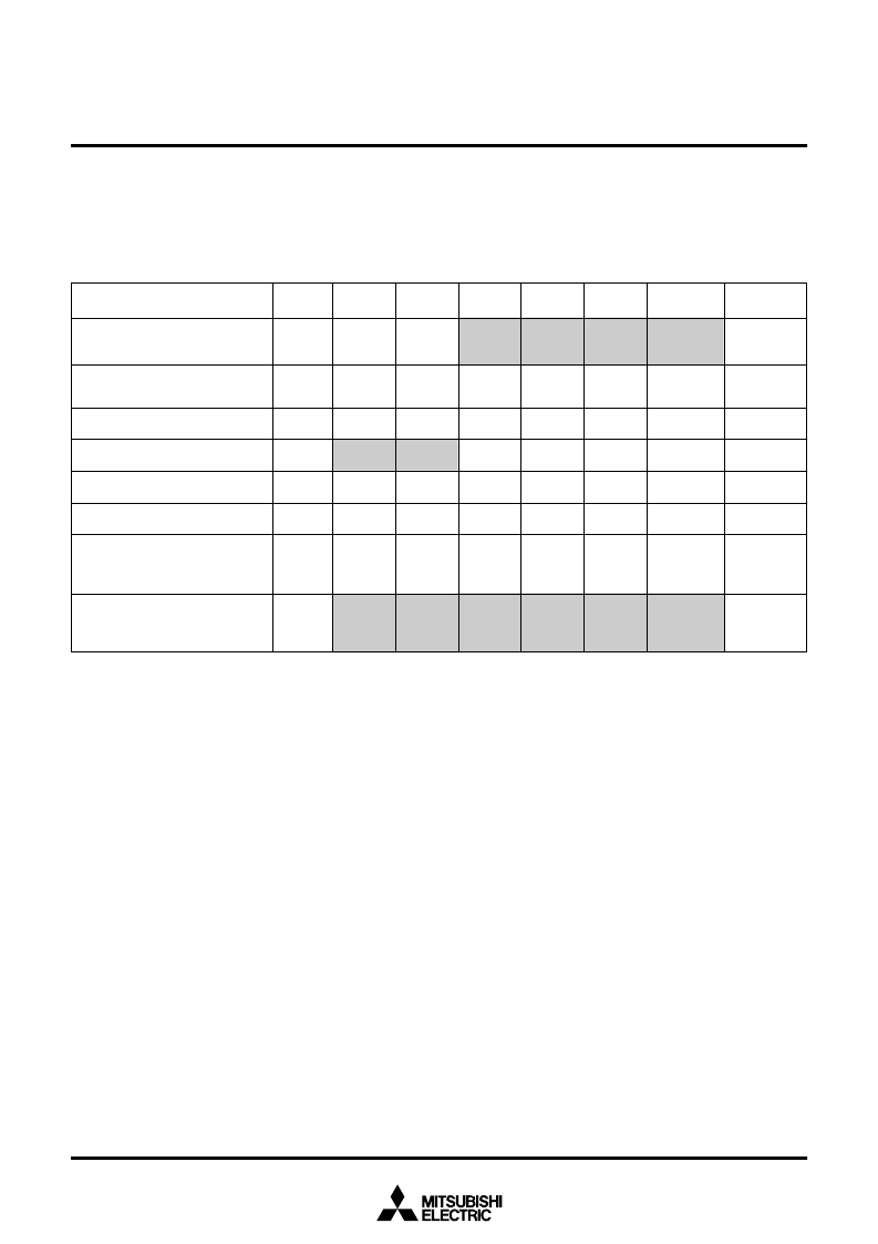
Table 15 lists software commands. In standard serial I/O mode,
erase, program and read are controlled by transferring software
2nd byte
Address
(middle)
3rd byte
Address
(high)
4th byte
Data
output
5th byte
Data
output
6th byte
Data
output
.....
Data
output to
259th byte
Data input
to 259th
byte
FF
16
When ID is
not verified
1st byte
transfer
Notes1:
Shading indicates transfer from the internal flash memory microcomputer to a programmer. All other data is transferred from an external equipment
(programmer) to the internal flash memory microcomputer.
2:
SRD refers to status register data. SRD1 refers to status register 1 data.
3:
All commands can be accepted when the flash memory is totally blank.
4:
Address high must be
“
00
16
”
.
commands via the RxD pin. Software commands are explained
here below.
Table 15 Software commands (Standard serial I/O mode)
1
Page read
41
16
Address
(middle)
Address
(high)
Data
input
Data
input
Data
input
Not
acceptable
Not
acceptable
A7
16
D0
16
70
16
SRD
output
SRD1
output
Acceptable
50
16
Not
acceptable
F5
16
Address
(low)
Address
(middle)
Address
(high)
ID size
ID1
To ID7
Acceptable
FA
16
Data
input
To
required
number
of times
Not
acceptable
FB
16
Version
data
output
Version
data
output
Version
data
output
Version
data
output
Version
data
output
Version
data output
to 9th byte
Control command
2
Page program
3
Erase all blocks
4
Read status register
5
Clear status register
6
ID code check
7
Download function
8
Version data output function
Size
(low)
Size
(high)
Check-
sum
Acceptable
Not
acceptable
相關(guān)PDF資料 |
PDF描述 |
|---|---|
| 386M-E1 | LOW VOLTAGE AUDIO POWER AMPLIFIER |
| 3886GROUP | SINGLE-CHIP 8-BIT CMOS MICROCOMPUTER |
| 38920000230 | Repeater |
| 38B5 | SINGLE-CHIP 8-BIT CMOS MICROCOMPUTER |
| 38C1 | DIODE ZENER SINGLE 200mW 24Vz 0.05mA-Izt 0.05 0.05uA-Ir 18.2 SOD-323 3K/REEL |
相關(guān)代理商/技術(shù)參數(shù) |
參數(shù)描述 |
|---|---|
| 3850 02 30 00 | 制造商:Lumberg Connect GmbH 功能描述: |
| 3850 07 00 02 | 制造商:Lumberg Connect GmbH 功能描述: |
| 3850 20 00 09 | 制造商:Lumberg 功能描述:21005 |
| 3850 A20928G | 制造商:LG Corporation 功能描述:LABEL, ENERGY |
| 3850(SPEC | 制造商:未知廠家 制造商全稱(chēng):未知廠家 功能描述:3850Group(Spec. H) USER'S MANUALHardware Manual & Device User's Manual 2969K/SEP.18.03 |
發(fā)布緊急采購(gòu),3分鐘左右您將得到回復(fù)。