- 您現(xiàn)在的位置:買賣IC網(wǎng) > PDF目錄382774 > ZR36053TQC30 Fast Recovery Rectifier Diodes PDF資料下載
參數(shù)資料
| 型號: | ZR36053TQC30 |
| 英文描述: | Fast Recovery Rectifier Diodes |
| 文件頁數(shù): | 11/16頁 |
| 文件大小: | 228K |
| 代理商: | ZR36053TQC30 |

ZR36011
11
PRELIMINARY
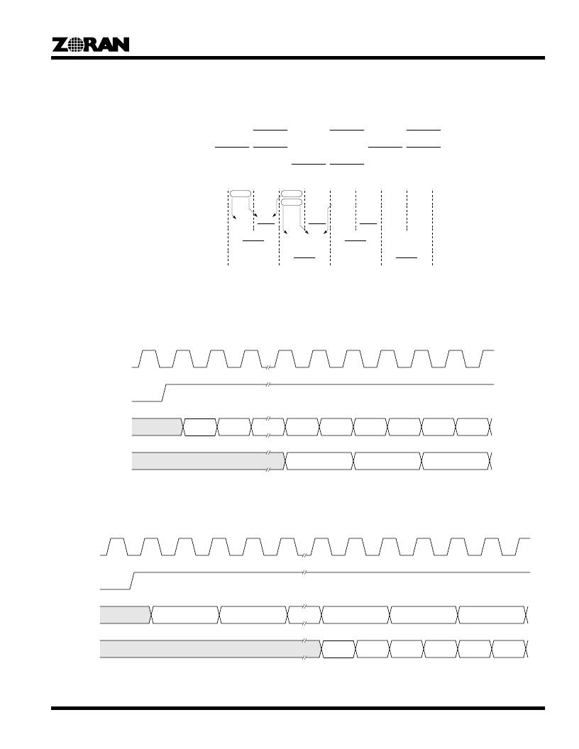
CHS determines the validity of input data and synchronizes the half-clock-rate data transitions on the Y, CR pins, and the multiplexing
of Cb and Cr. As shown in Figure 20 for forward conversion, and Figure 21 for inverse conversion, the second rising edge of CLK
following the rising edge of CHS latches the first valid input data sample.
Data Input:
Y
Y
Y0
Cb0
CR
Y1
Cr1
Y2
Cb2
Figure 19. Illustration of Interpolation, MODE = 111
Y (N)
Cb (N)
Y (N)
Cb (N)
Interpolator Output:
Y3
Cr3
CR
Y (N+1)
Cr (N+1)
Y (N+1)
Cr (N+1)
Y (N+2)
Cb (N+2)
Y(N)
Cb(N)
Cr(N+1)+Cr(N-1)
2
Y0
Cb0
Y0+Y1
2
Cr-1+Cr1
2
Y1
Cr1
Y1+Y2
2
Cb0+Cb2
2
Y2
Cb2
Y2+Y3
2
Cr1+Cr3
2
Y3
Cr3
Y (N+2)
Cb (N+2)
Y(N)+Y(N+1)
2
Cr(N+1)+Cr(N-1)
2
Cb(N)
Y(N+1)
Cb(N)+Cb(N+2)
2
Cr(N+1)
Y(N+1)+Y(N+2)
2
Cr(N+1)
Cb(N)+Cb(N+2)
2
Y(N+2)
Cr(N+3)+Cr(N+1)
2
Cb(N+2)
Y(N+2)+Y(N+3)
2
Cr(N+3)+Cr(N+1)
2
Cb(N+2)
Cb2+Cb4
2
CLK
Y, CR
(Output)
R, G, B
(Input)
Figure 20. RGB to YCbCr Timing, MODE = 111
RGB
(0)
Y(0), Cb (0)
CHS
RGB
(1)
RGB
(8)
RGB
(9)
RGB
(10)
RGB
(11)
RGB
(12)
RGB
(13)
Y(2), Cr (2)
Y(4), Cb (4)
CLK
R, G, B
(Output)
Y, CR
(Input)
Figure 21. YCbCr to RGB timing, MODE = 111
RGB
(0)
Y(0), Cb (0)
CHS
RGB
(1)
RGB
(2)
RGB
(3)
RGB
(4)
RGB
(5)
Y(2), Cr (2)
Y(8), Cb (8)
Y(10), Cr (10)
Y(12), Cb (12)
相關PDF資料 |
PDF描述 |
|---|---|
| ZR36055PQC21 | |
| ZR36055PQC29.5 | |
| ZR36057PQC | |
| ZR36060PQC-27 | |
| ZR36060PQC-29.5 | |
相關代理商/技術參數(shù) |
參數(shù)描述 |
|---|---|
| ZR36055PQC21 | 制造商:未知廠家 制造商全稱:未知廠家 功能描述: |
| ZR36055PQC29.5 | 制造商:未知廠家 制造商全稱:未知廠家 功能描述: |
| ZR36057 | 制造商:ZORAN 制造商全稱:ZORAN 功能描述:ENHANCED PCI BUS MULTIMEDIA CONTROLLER |
| ZR36057PQC | 制造商:ZORAN 制造商全稱:ZORAN 功能描述:ENHANCED PCI BUS MULTIMEDIA CONTROLLER |
| ZR36060 | 制造商:未知廠家 制造商全稱:未知廠家 功能描述:Integrated JPEG CODEC |
發(fā)布緊急采購,3分鐘左右您將得到回復。