- 您現(xiàn)在的位置:買賣IC網(wǎng) > PDF目錄358534 > VF140B-1-11.0592MHZ (VALPEY FISHER CORP) CRYSTAL OSCILLATOR, CLOCK, 11.0592 MHz, HCMOS/TTL OUTPUT PDF資料下載
參數(shù)資料
| 型號(hào): | VF140B-1-11.0592MHZ |
| 廠商: | VALPEY FISHER CORP |
| 元件分類: | XO, clock |
| 英文描述: | CRYSTAL OSCILLATOR, CLOCK, 11.0592 MHz, HCMOS/TTL OUTPUT |
| 封裝: | HERMETIC SEALED PACKAGE-4 |
| 文件頁數(shù): | 1/1頁 |
| 文件大小: | 22K |
| 代理商: | VF140B-1-11.0592MHZ |
X O
VF140
75 South Street, Hopkinton, MA 01748 800-982-5737 508-435-6831 Fax: 508-435-5289 www.valpeyfisher.com
54
Creating a Part Number
VF140
INPUT VOLTAGE
Code
L
Specification
3.3 Volt
5.0 Volt (std.)
OUTPUT
Code
T
Specification
Tristate
Std.
FREQUENCY STABILITY
Code
S
A
B
Specification
±
20
ppm
±
25
ppm
±
50
ppm
±
100
ppm (std.)
±
500
ppm
C
DUTY CYCLE
Code
HH
H
Specification
±
2.5%
±
5%
±
10% (std.)
OPERATIONAL TEMP. RANGE
Code
1
2
Specification
0
°
C to +70
°
C (std.)
-40
°
C to +85
°
C
-55
°
C to +125
°
C*
*Not always available
FREQ.
10%, Input Voltage 3.3 Volt
±
5%, Operating Temperatu50ppm, Duty Cycle
C to +85
°
C,
Output Non-Tristate, Lead Configuration Straight, Frequency 1.8432MHz.
LEAD CONFIGURATION
Code
G
Specification
Gull Wing
Through hole
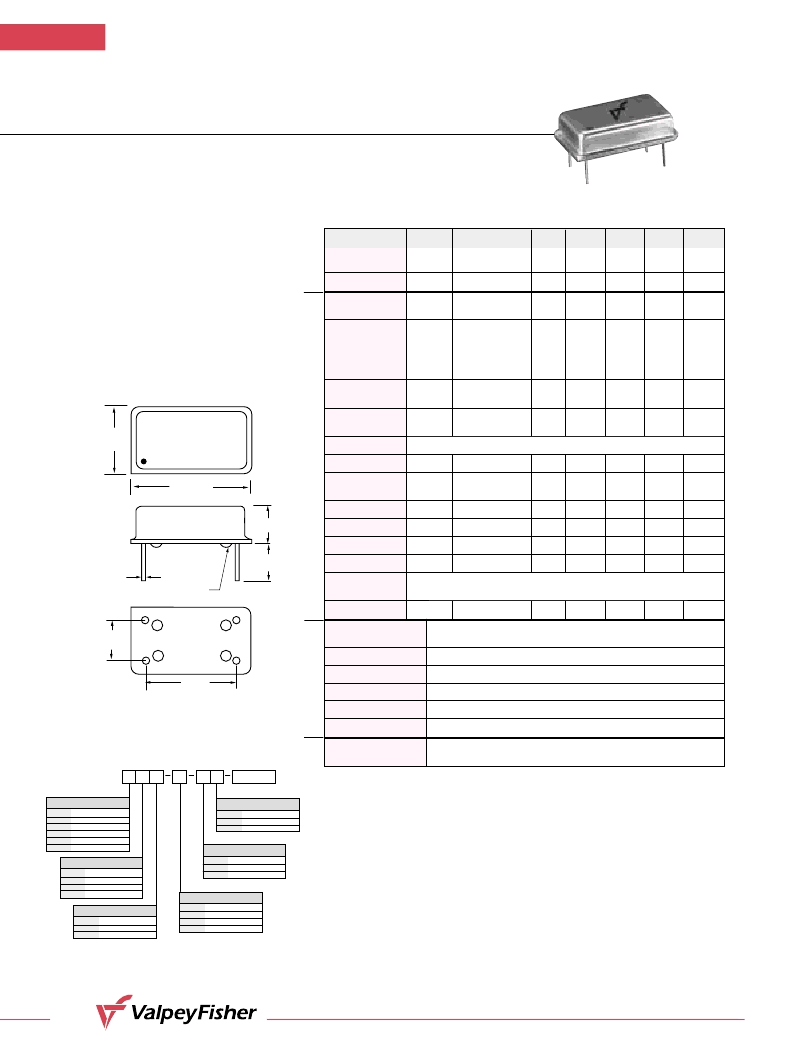
(20.800"
(0.300"
#1
#7
#8
#14
0.600"
(15,24mm)
GLASS STANDOFFS
0.497"
(12,62mm)
0.254"
(6,45mm)
VF140
1.8432MHZ
BO1H
(0.250"
0.0180"
0.002"
(0,460mm
±
0,051mm)
V F140
HCMOS/TTL Compatible
Clock Oscillators
F E A T U R E S
Tristate Output Available
Low Cost
Industrial and Military
Temperature Available
Wide Frequency Range
Very Low Phase Jitter
Parameter
Symb
Condition
Min
Typ
Max
Unit
Note
Input Break
Down Voltage
Vcc
–0.5
7.0
V
Storage Temp.
Ts
–55
+125
°C
Frequency
Range
F
0.2
130
MHz
Frequency
Stability
F/F
Overall conditions
including:
calibration, temp.,
aging 10 yrs,
shock, vibration
±100
ppm
1
Input Voltage
Vcc
4.75
3.15
5.00
3.30
5.25
3.45
V
Std.
LV Opt.
Input Current
Icc
F = 50MHz
15pF, load Vcc 5V
40
mA
2
Load
Duty Cycle
@1.4V
40
50
60
%
3
Rise/Fall Time
Tr/Tf
0.4V to 2.4V
20% to 80%
1.5
4.0
ns
Logic “1” Level
Voh
Max Load
0.9Vcc
V
Logic “0” Level
Vol
Max Load
0.1Vcc
V
Start–up Time
Ts
2
10
ms
Phase Jitter
1
σ
1
ps
fj>1KHz
Tristate
Function
Enable Time
100
ns
Operating
Temperature Range
0°C to +70°C (–40°C to +85°C, –55°C to +125°C available)
Mechanical Shock
Per MIL–STD–202, Method 213, Cond. E
Thermal Shock
Per MIL–STD–883, Method 1011, Cond. A
Vibration
Per MIL–STD–883, Method 2007, Cond. A
Soldering Conditions
260°C, for 10s, Max.
Hermetic Seal
Leak rate less than 5 x 10
–8
atm.cc/s of helium
Pin Out
Pin #1–Tristate Control or N/C
Pin #3–Output
Pin #2–Ground, Case
Pin #4–Vcc
10 TTL gates or 50pF Max.
A
M
E
E
a
E
C
Notes:
1. Standard frequency stability (±20, ±25, ±50, others available).
2. Current is load and frequency dependent.
3. Tighter duty cycles available.
All specifications are subject to change without notice.
All dimensions are typical unless otherwise specified.
Input HIGH (>2.5V) or floating:
Input LOW (<0.5V):
ACTIVE
INFINITE IMPEDANCE
相關(guān)PDF資料 |
PDF描述 |
|---|---|
| VF161A-1-FREQ | CRYSTAL OSCILLATOR, CLOCK, 10 MHz - 300 MHz, PECL OUTPUT |
| VF160HH-G-FREQ | CRYSTAL OSCILLATOR, CLOCK, 10 MHz - 300 MHz, ECL OUTPUT |
| VF161HH-FREQ | CRYSTAL OSCILLATOR, CLOCK, 10 MHz - 300 MHz, PECL OUTPUT |
| VF161B-1G-FREQ | CRYSTAL OSCILLATOR, CLOCK, 10 MHz - 300 MHz, PECL OUTPUT |
| VF161HH-CEG-FREQ | CRYSTAL OSCILLATOR, CLOCK, 10 MHz - 300 MHz, PECL OUTPUT |
相關(guān)代理商/技術(shù)參數(shù) |
參數(shù)描述 |
|---|---|
| VF140B2 | 制造商:未知廠家 制造商全稱:未知廠家 功能描述:Peripheral IC |
| VF140B-70.000MHZ | 制造商:VALPEY_FISHER 功能描述: |
| VF140C | 制造商:未知廠家 制造商全稱:未知廠家 功能描述:Peripheral IC |
| VF140C1 | 制造商:未知廠家 制造商全稱:未知廠家 功能描述:Peripheral IC |
| VF140C2 | 制造商:未知廠家 制造商全稱:未知廠家 功能描述:Peripheral IC |
發(fā)布緊急采購(gòu),3分鐘左右您將得到回復(fù)。