- 您現(xiàn)在的位置:買賣IC網(wǎng) > PDF目錄358534 > VF161HH-CEG-FREQ (VALPEY FISHER CORP) CRYSTAL OSCILLATOR, CLOCK, 10 MHz - 300 MHz, PECL OUTPUT PDF資料下載
參數(shù)資料
| 型號: | VF161HH-CEG-FREQ |
| 廠商: | VALPEY FISHER CORP |
| 元件分類: | XO, clock |
| 英文描述: | CRYSTAL OSCILLATOR, CLOCK, 10 MHz - 300 MHz, PECL OUTPUT |
| 文件頁數(shù): | 1/1頁 |
| 文件大?。?/td> | 24K |
| 代理商: | VF161HH-CEG-FREQ |
75 South Street, Hopkinton, MA 01748 800-982-5737 508-435-6831 Fax: 508-435-5289 www.valpeyfisher.com
57
X O
VF160/ 161E
V F160–E/V F161–E
10KH ECL/PECL Compatible
Enable/Disable Clock Oscillator
F E A T U R E S
Enable/Disable Output
Industrial Temperature Range
In–house “Inverted Mesa” Crystal
Technology for Higher Frequencies
Wide Frequency Range
Very Low Phase Jitter
Parameter
Symb
Condition
Min
Typ
Max
Unit
Note
Input Break
Down Voltage
Vcc–Vee
–0.5
7.0
V
Storage Temp.
Ts
–40
+85
°C
Frequency
Range
F
10
300
MHz
Frequency
Stability
F/F
Overall Conditions
Including:
Calibration, temp.,
aging 10 yrs.
shock, vibration
±100
ppm
1
Input Voltage
Vcc
Vcc
Vee
PECL
LVPECL
ECL
4.75
3.15
–4.95
5.00
3.30
–5.20
5.25
3.45
–5.45
V
VF161E
VF161L–E
VF160E
Input Current
Icc/Iee
50 Ohm Load
50 Ohm to Vcc–2V or Thevenin Equiv. Bias required
80
mA
Load
Duty Cycle
@50%
45
50
55
%
2
Rise/Fall Time
Tr/Tf
20% to 80%
1.5
ns
Logic “1” Level
Voh
@Vcc = 5.0V
@Vee = –5.2V
@Vcc = 3.3V
4.04
–0.96
2.59
4.19
–0.81
2.74
V
PECL
ECL
LVPECL
Logic “0” Level
Vol
@Vcc = 5.0V
@Vee = –5.2V
@Vcc = 3.3V
3.15
–1.85
1.45
3.25
–1.65
1.55
V
PECL
ECL
LVPECL
Start–up Time
Ts
2
10
ms
Phase Jitter
1
σ
1
ps
fj>1KHz
Enable/
Disable Function
Operating
Temperature Range
0°C to +70°C (–40°C to +85°C available)
Mechanical Shock
Per MIL–STD–202, Method 213, Cond. E
Thermal Shock
Per MIL–STD–883, Method 1011, Cond. A
Vibration
Per MIL–STD–883, Method 2007, Cond. A
Soldering Conditions
260°C, for 10s, Max.
Hermetic Seal
Leak rate less than 5 x 10
–8
atm.cc/s of helium
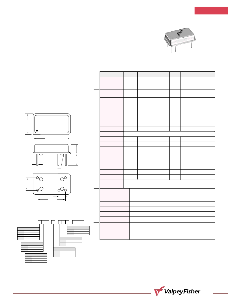
Pin Out
Pin #1–Enable/Disable Control
Pin #7–Ground, Case (PECL)/Vee (ECL)
Pin #8–Output
Pin #9–Optional – Complementary output
Pin #14–Vcc (PECL)/Ground, Case (ECL)
A
M
E
E
a
E
C
Creating a Part Number
VF160/161
OUTPUT
Code
C
Specification
Complementary
Single output (std.)
INPUT VOLTAGE
Code
L
Specification
3.3 Volt
±
5%
5.0 Volt
±
5% (std.)
OPERATIONAL TEMP. RANGE
Code
1
Specification
0
°
C to +70
°
C (std.)
-40
°
C to +85
°
C
FREQUENCY STABILITY
Code
S
A
B
Specification
±
20
ppm
±
25
ppm
±
50
ppm
±
100
ppm (std.)
DUTY CYCLE
Code
HH
Specification
±
2.5%
±
5%
E
FREQ.
2.5%, Input Voltage 3.3 Volt
20pC to +85
±
5%, Operating Temperature -40
°
C,
Complementary Output, Enable/Disable, Frequency 200.000MHz.
LEAD CONFIGURATION
Code
G
Specification
Gull Wing
Through Hole (std.)
0.800"
(20,32mm)
0.300"
(7,62mm)
#1
#7
#8
#9
#14
0.600"
(15,24mm)
GLASS STANDOFFS
0.497"
(12,62mm)
0.187"
(4,75mm)
0.0180"
(0,460mm)
VALPEYFISHER
VF161-E
200MHZ
BO1H
0.250"
(6,35mm)
0.100"
(2,54mm)
Control input “Vee” or floating
Control input “High”
– Enable
– Disable Low
Notes:
1. Standard frequency stability (±20, ±25, ±50, others available).
2. Tighter duty cycles available. Measure @ 50% of the voltage swing.
3. Pin #9 omitted if complementary output is not specified.
All specifications are subject to change without notice.
All dimensions are typical unless otherwise specified.
相關PDF資料 |
PDF描述 |
|---|---|
| VF161HHL-CEG-FREQ | CRYSTAL OSCILLATOR, CLOCK, 10 MHz - 300 MHz, LVPECL OUTPUT |
| VF160A-CEG-FREQ | CRYSTAL OSCILLATOR, CLOCK, 10 MHz - 300 MHz, ECL OUTPUT |
| VF261SL-1-FREQ-OUT33 | CRYSTAL OSCILLATOR, CLOCK, 15 MHz - 300 MHz, LVPECL OUTPUT |
| VF266B-1-212.5MHZ | CRYSTAL OSCILLATOR, CLOCK, 212.5 MHz, LVPECL OUTPUT |
| VF267-A-1-FREQ | CRYSTAL OSCILLATOR, CLOCK, 25 MHz - 320 MHz, LVPECL OUTPUT |
相關代理商/技術參數(shù) |
參數(shù)描述 |
|---|---|
| VF161R | 制造商:未知廠家 制造商全稱:未知廠家 功能描述:Peripheral IC |
| VF161R1 | 制造商:未知廠家 制造商全稱:未知廠家 功能描述:Peripheral IC |
| VF161R2 | 制造商:未知廠家 制造商全稱:未知廠家 功能描述:Peripheral IC |
| VF161RA | 制造商:未知廠家 制造商全稱:未知廠家 功能描述:Peripheral IC |
| VF161RA1 | 制造商:未知廠家 制造商全稱:未知廠家 功能描述:Peripheral IC |
發(fā)布緊急采購,3分鐘左右您將得到回復。