- 您現(xiàn)在的位置:買賣IC網(wǎng) > PDF目錄383986 > USB97C223 (SMSC Corporation) capacitor Selection for Internal Regulator Output Pins PDF資料下載
參數(shù)資料
| 型號: | USB97C223 |
| 廠商: | SMSC Corporation |
| 英文描述: | capacitor Selection for Internal Regulator Output Pins |
| 中文描述: | 電容的選擇內(nèi)部穩(wěn)壓器輸出引腳 |
| 文件頁數(shù): | 38/59頁 |
| 文件大小: | 385K |
| 代理商: | USB97C223 |
第1頁第2頁第3頁第4頁第5頁第6頁第7頁第8頁第9頁第10頁第11頁第12頁第13頁第14頁第15頁第16頁第17頁第18頁第19頁第20頁第21頁第22頁第23頁第24頁第25頁第26頁第27頁第28頁第29頁第30頁第31頁第32頁第33頁第34頁第35頁第36頁第37頁當前第38頁第39頁第40頁第41頁第42頁第43頁第44頁第45頁第46頁第47頁第48頁第49頁第50頁第51頁第52頁第53頁第54頁第55頁第56頁第57頁第58頁第59頁
SMSC DS – USB97C201
Page 38
Rev. 03/25/2002
PRELIMINARY
USB_ERR
(0xDA - RESET=0x00)
NAME
USB ERROR REGISTER
DESCRIPTION
BIT
R/W
has been received on an endpoint.
Note:
Writing a “1” to a bit in this register will clear the bit.. If any bit is set in this register the USB_ERR bit is set in
the USB_STAT register.
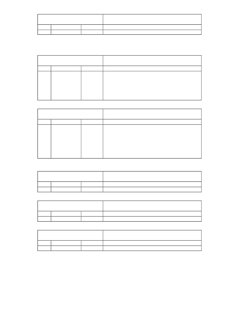
Table 51 – MSB ATA Data Register
MSB_ATA
(0xDB - RESET=0x00)
NAME
D[15:8]
MSB ATA CONTROL/STATUS DATA REGISTER
DESCRIPTION
During 8051 writes to XDATA 0x31F0 (the ATA Drives
Control/Status register), data in this register represents the
MS byte of the 16 bit operation to this address. For a read
of 0x31F0, the MS byte data is returned in this register after
the PIO_COMPLETE bit is set in the ATA_CTL register. (the
data returned from the actual read of 31F0 should be
discarded)
BIT
[7:0]
R/W
R/W
Table 52 – LSB ATA Data Register
LSB_ATA
(0xDC - RESET=0x00)
NAME
D[7:0]
LSB ATA CONTROL/STATUS DATA REGISTER
DESCRIPTION
During 8051 reads to XDATA 0x31F1-7 and 33F6 (the ATA
Drive’s 8 bit registers), the actual data is returned in this
register after the PIO_COMPLETE bit is set in the ATA_CTL
register. During writes, this register is unused.
For 8051 read to XDATA 0x31F0, the LS byte of data is
returned in this register after the PIO_COMPLETE bit is set
in the ATA_CTL register. During writes, this register is
unused.
BIT
[7:0]
R/W
R/W
Table 53 – ATA Transfer Count Register 0
ATA_CNT0
(0xE1 - RESET=0x00)
NAME
D[7:0]
ATA TRANSFER COUNT REGISTER 0
DESCRIPTION
See note below.
BIT
[7:0]
R/W
R/W
Table 54 – ATA Transfer Count Register 1
ATA_CNT1
(0xE2 - RESET=0x00)
NAME
D[15:8]
ATA TRANSFER COUNT REGISTER 1
DESCRIPTION
See note below.
BIT
[7:0]
R/W
R/W
Table 55 – ATA Transfer Count Register 2
ATA_CNT2
(0xE3 - RESET=0x00)
NAME
D[23:16]
ATA TRANSFER COUNT REGISTER 2
DESCRIPTION
See note below.
BIT
[7:0]
R/W
R/W
相關(guān)PDF資料 |
PDF描述 |
|---|---|
| USB97C243 | capacitor Selection for Internal Regulator Output Pins |
| USB97CFDC | USB FLOPPY DISK CONTROLLER |
| USH-1000-KS | Lamps for Photolithography |
| USH1000FAL2 | Lamps for Photolithography |
| USH1002FGL | Lamps for Photolithography |
相關(guān)代理商/技術(shù)參數(shù) |
參數(shù)描述 |
|---|---|
| USB97C223-NE | 制造商:SMSC 制造商全稱:SMSC 功能描述:Bus Powered USB 2.0 Flash Media Controller |
| USB97C223-NU | 制造商:SMSC 制造商全稱:SMSC 功能描述:Bus Powered USB 2.0 Flash Media Controller |
| USB97C242 | 制造商:SMSC 制造商全稱:SMSC 功能描述:USB 2.0 Flash Drive Controller |
| USB97C242-MN | 制造商:SMSC 制造商全稱:SMSC 功能描述:USB 2.0 Flash Drive Controller |
| USB97C242-MN-03 | 制造商:Rochester Electronics LLC 功能描述:- Bulk 制造商:SMSC 功能描述: |
發(fā)布緊急采購,3分鐘左右您將得到回復。