- 您現(xiàn)在的位置:買賣IC網(wǎng) > PDF目錄1971 > USB-I2C-DIL (Flexipanel)IC USB SYNC SRL I2C 28-DIL PDF資料下載
參數(shù)資料
| 型號(hào): | USB-I2C-DIL |
| 廠商: | Flexipanel |
| 文件頁(yè)數(shù): | 2/9頁(yè) |
| 文件大?。?/td> | 0K |
| 描述: | IC USB SYNC SRL I2C 28-DIL |
| 標(biāo)準(zhǔn)包裝: | 25 |
| 應(yīng)用: | USB |
| 接口: | I²C |
| 電源電壓: | 1.8 V ~ 5 V |
| 封裝/外殼: | 28-DIP |
| 供應(yīng)商設(shè)備封裝: | 28-DIL |
| 包裝: | 散裝 |
| 安裝類型: | 通孔 |
| 其它名稱: | 658-1036-5 |
p2 of 9
26-Aug-10
USB-SPI
HW144-8
www.hexwax.com
Basic Operation
To the electronic system (‘device’), USB-I2C looks like a
I2C serial slave device. To the PC (‘host’), it looks like a
Human Interface Device (HID) with which it may
exchange information using simple commands. When
the data is sent to USB-I2C from the device using its
write address, the data is buffered and sent to the PC.
When it is addressed by the device using its read
address, any data sent from the PC is output to the
device.
Using the HID USB profile means that no driver
installation is required and immediate compatibility is
assured on Windows, Linux and OS systems.
Additionally, software can find the device automatically
without needing to know which virtual COM port it is
occupying.
Pin Functions
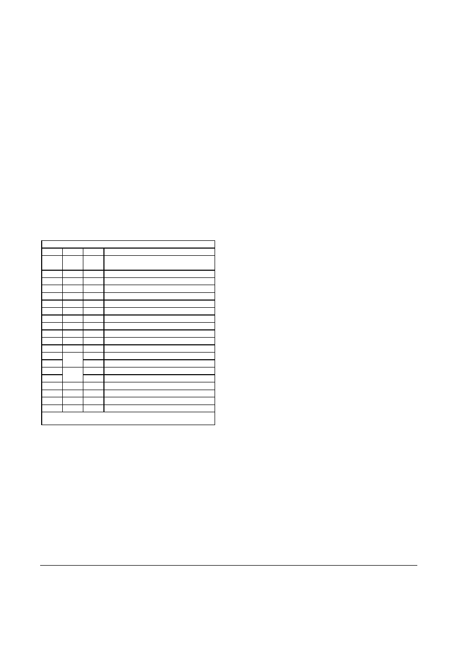
The pin functions are shown in table 2. The function of
the virtual I/O pins is reconfigurable, so their default
settings are also shown. Note that the output pins are in
a tri-state condition until ~20μs after power-on.
Table 2. Device Pinout
DIL
SSOP Name Description
1
4
VIO0
Vpp
Virtual I/O / *Reset# (in)
TEAclipper Vpp
5
VIO1
Virtual I/O / *Tx Ind (out)
6
VIO2
Virtual I/O / *Rx Ind (out)
11
7
VIO3
Virtual I/O / *Tx/Rx Ind (out)
12
10
VIO4
Virtual I/O / *All-Systems-Go# (out)
22
11
SCL
Slave serial data clock input
13
12
VIO5
Virtual I/O / *Suspend# (out)
21
13
SDA
Slave serial data input / output
17
14
VIO8
Virtual I/O / *Tx Buffer Empty (out)
23
15
VIO9
Virtual I/O / *Send (int)
24
16
VIO10 Virtual I/O / *Rx Buffer Not Full (out)
14
17
Vusb
USB supply filter
15
D-
USB data -
27
18
PGC
TEAclipper PGC
16
D+
USB data+
28
19
PGD
TEAclipper PGD
8,19
20
Vss
Power ground reference
20
1
Vdd
Power positive input
9
3
OSC1 Oscillator output
10
2
OSC2 Oscillator input
* = default configuration
# = active low
The pin functions are described in detail below.
Vss, Vdd, Vusb
Vss is the power supply ground reference. Vdd should
be connected to a regulated supply, for example the
USB bus power.
Vusb should be connected, via a
470nF capacitor, to Vss. See for example C8 in figure 2.
OSC1, OSC2
OSC1 and OSC2 should be connected to a 12MHz
parallel cut crystal circuit with 22pF capacitors. It may
be replaced with a 12MHz resonator with 0.25% total
tolerance.
SCL, SCK
I2C serial data I/O. Data is input or output on SDA
according to the read/write address. The SCL input
provides synchronization according to usual I2C
standards. The I2C default read/write addresses are
0x27 and 0x26 respectively; these values may be
changed using the HIDconfig.exe application.
Vpp, PGC, PCD
TEAclipper programming pins. Refer to the Delivery
and Programming section for details. Note that the Vpp
pin may be subject to voltages as high as 12V during
programming.
VIO pins
The VIO pin functions can be reconfigured as detailed in
the customization section. The default functions are
shown in table 2. The pins can be configured as follows.
No Function
The pin is a digital input that has no effect. To minimize
power consumption, it should be biased high or low.
This setting is available on all VIOs.
Reset
The pin is an active low reset input.
Resetting the
device effectively implements the soft detach function.
This setting is available on VIO0 only.
USB Power Sense
If the device is capable of operating while not plugged
into a USB port, a USB Power Sense input should be
provided.
This pin should indicate that a voltage is
detected on the V+ pin of the USB connector. It is used
to reduce power consumption by entering into a sleep
mode when the USB is not present, and also to ensure
that the USB engine correctly initializes when the device
is plugged in. The I2C port is not operational during
sleep. This setting must be on VIO9.
Self Power Sense
If the device is capable of operating while not plugged
into a USB port, a Self Power Sense input may be
provided. This pin should indicate when the device is
not drawing power from the USB bus and can help the
PC manage its power budget. This setting is available
on any VIO pin.
Tx Indication
Output for connecting to a transmit indication LED. It
turns on for approximately 100ms when data has been
transmitted to the host. This setting is available on any
VIO pin except VIO0.
Rx Indication
Output for connecting to a receive indication LED. It
turns on for approximately 100ms when data has been
received from the host. This setting is available on any
VIO pin except VIO0.
Tx / Rx Indication
Output for connecting to a transmit / receive indication
LED. It turns on for approximately 100ms when data
相關(guān)PDF資料 |
PDF描述 |
|---|---|
| USB-SPI-DIL | IC USB SYNC SRL SPI 28-DIL |
| USB2SERA10CFK | USB TO SERIAL BRIDGE |
| V62/11608-01XE | IC SWITCH SPDT SGL 8PIN |
| VNC2-64Q1B-TRAY | IC USB HOST/DEVICE CTRL 64-QFN |
| W78E858A40FL | IC MCU 8-BIT 32K FLASH 44-PQFP |
相關(guān)代理商/技術(shù)參數(shù) |
參數(shù)描述 |
|---|---|
| USB-I2C-SS | 功能描述:USB 接口集成電路 Driver-free USB to serl SPIslve intrfce RoHS:否 制造商:Cypress Semiconductor 產(chǎn)品:USB 2.0 數(shù)據(jù)速率: 接口類型:SPI 工作電源電壓:3.15 V to 3.45 V 工作電源電流: 最大工作溫度:+ 85 C 安裝風(fēng)格:SMD/SMT 封裝 / 箱體:WLCSP-20 |
| USB-ICP-80C51ISP | 功能描述:程序設(shè)計(jì)器 - 基于處理器 In-System Programmer for NXP 80C51ISP RoHS:否 制造商:Olimex Ltd. 產(chǎn)品:Programmers 工具用于評(píng)估:XMEGA, MegaAVR, tinyAVR 核心:AVR 接口類型:USB 工作電源電壓:1.8 V to 5.5 V |
| USB-ICP-LPC2K | 功能描述:程序設(shè)計(jì)器 - 基于處理器 In-System Programmer for NXP ARM7 LPC2xxx RoHS:否 制造商:Olimex Ltd. 產(chǎn)品:Programmers 工具用于評(píng)估:XMEGA, MegaAVR, tinyAVR 核心:AVR 接口類型:USB 工作電源電壓:1.8 V to 5.5 V |
| USB-ICP-LPC9XX | 功能描述:程序設(shè)計(jì)器 - 基于處理器 In-Circuit Programer for NXP LPC9xx RoHS:否 制造商:Olimex Ltd. 產(chǎn)品:Programmers 工具用于評(píng)估:XMEGA, MegaAVR, tinyAVR 核心:AVR 接口類型:USB 工作電源電壓:1.8 V to 5.5 V |
| USB-ICP-SAB9 | 功能描述:插座和適配器 Socket Adapter Brd USB-ICP-LPC9xx Drvr RoHS:否 制造商:Silicon Labs 產(chǎn)品:Adapter 用于:EM35x |
發(fā)布緊急采購(gòu),3分鐘左右您將得到回復(fù)。