- 您現(xiàn)在的位置:買賣IC網(wǎng) > PDF目錄4568 > USB-DAQ-SS (Flexipanel)IC SYSTEM DATA LOGGER 20-SSOP PDF資料下載
參數(shù)資料
| 型號(hào): | USB-DAQ-SS |
| 廠商: | Flexipanel |
| 文件頁(yè)數(shù): | 6/8頁(yè) |
| 文件大小: | 0K |
| 描述: | IC SYSTEM DATA LOGGER 20-SSOP |
| 標(biāo)準(zhǔn)包裝: | 25 |
| 系列: | * |
| 其它名稱: | 658-1042-5 |

p6 of 8
26-Aug-10
USB-DAQ
HW147-5
www.hexwax.com
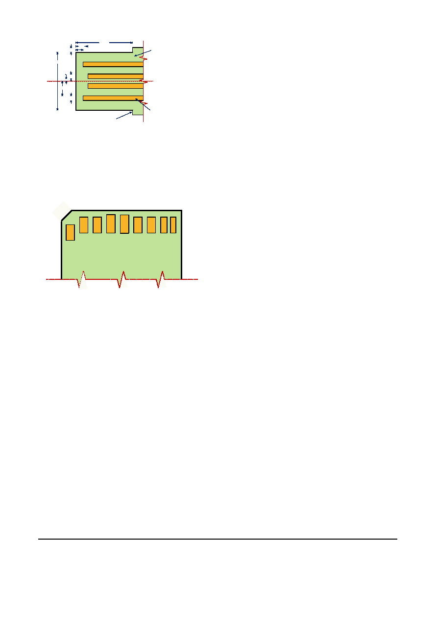
4. Vss
11.75
1.00-2.00
1.00
0.50
3.00
12.00
Shoulder required to prevent over-insertion
Overall PCB width 16.00 or less
Contacts plated with hard
gold flash (0.25-1.27m)
over nickel (2.6-5.0m)
Overall PCB thickness
including tracks 2.00 - 2.20
3. D+
2. D-
1. Vdd
2.25
1.25
Dimensions in mm
Figure 6. Integral USB connector dimensions
For further dimensional information, refer to figure 6-7 of
the USB 2.0 Specification, in the development kit.
SD Card Connector
The SPI connections for SD cards is shown in figure 7.
The two pins marked BH are unused and should be
biased high or left unconnected.
6
.V
ss
2
.M
O
S
I
1
.C
S
#
3
.V
ss
4
.V
dd
5
.S
C
K
7
.M
IS
O
8
.B
H
9.
B
H
Figure 7. SD Card Connections.
Pin 9 is out of order; this is not an error.
Device Programming
USB-DAQ is programmed from the Excel Spreadsheet
USB-DAQ Complier.xls. In it, you can specify general
device configuration, application code and application
data.
After compilation, USB-DAQ creates a hidden
application file called CONFIG.DAT and any data
logging files you may have specified. To program the
USB-DAQ, copy these files to the device. (A write lock
option can be specified to prevent further tampering if
required.)
This section provides an overview of the various
elements of the compilation process. Refer to the USB-
DAQ
Compiler.xls
spreadsheet
and
the
base
microcontroller data sheets for full details. Also see the
examples in the development kit.
Device Configuration
The device configuration section of the spreadsheet
allows general settings to be specified, including:
- Device / Company name
- Real time clock settings
- Memory settings
- Application execution settings
- Data logging files
- Daylight savings settings
- Write protect & Escape pin
Write protect will permanently render USB-DAQ
unmodifiable by the PC. It is intended for completed
commercial applications only, to ensure the user does
not accidentally delete the files.
If write protect is set and an attempt is made to modify
or delete files, USB-DAQ will report that the files were
successfully modified, even though they were not. This
is necessary to enable to time to be set by appearing to
modify a file. Due to file caching by the PC, the file may
appear to be modified until USB-DAQ is removed and
re-inserted.
During development, the use of an Escape pin is
strongly recommended.
It ensures you can always
recover the USB-DAQ if your code unintentionally locks
the device. Failure to do so risks rendering the device
useless. If both write protect and the escape pin are
enabled, escape takes precedence and allows the write-
protected device to be modified.
Source Code
The source code section specifies the code to execute
during initialization and when an event occurs.
The
following instructions are provided:
- ADD, SUB, MULT, DIV, MOD, INC, DEC, COPY
- AND, OR, XOR, COMP, NEG, ROTL, ROTR
- FOR, NEXT, DO, WHILE, BREAK, CONTINUE
- IF, ELSEIF, ELSE, ENDIF
- CALL, RETURN, GOTO, ONERROR
- CLEARFILE, SETFILE, READ
- WRITEB, WRITEHEX, WRITEDEC, WRITER
- DELAY, RESET, SLEEP
- GETAN, GETBIT, SETBIT
- GETEE, SETEE, LOOKUP
- GETAT, SETAT
Registers
Most operations are associated with registers. Available
registers include:
- 56 bytes general random access memory, usable
as 1/2/4-byte, signed/unsigned integers
- 21 bytes of DAQ status registers, including flags,
error status, and time and date values
- Most
of
the
registers
of
the
underlying
microcontroller, including ports, peripherals and
interrupt control. (The underlying controllers are
PIC18F2550
for
the
28-pin
device
and
PIC18F14K50 for the 20-pin device.)
Non-Volatile Memory
Two sections of non-volatile memory are available:
- 64 bytes of EEPROM may be written and read by
the application
- Program code space can contain read-only data
that the application can read with the LOOKUP
and WRITER instructions.
相關(guān)PDF資料 |
PDF描述 |
|---|---|
| NCP698SQ13T1G | IC REG LDO 1.3V .28A SC-82AB |
| HMC30DRAH-S734 | CONN EDGECARD 60POS .100 R/A PCB |
| LFXP20E-5F256C | IC FPGA 19.7KLUTS 188I/O 256-BGA |
| LFXP20E-4FN256I | IC FPGA 19.7KLUTS 256FPBGA |
| LFXP20E-4F256I | IC FPGA 19.7KLUTS 188I/O 256-BGA |
相關(guān)代理商/技術(shù)參數(shù) |
參數(shù)描述 |
|---|---|
| USBDESKTOP | 制造商:ETI Systems 功能描述:Joystick;3-Axis;10 Programmable Buttons;Desktop Housing;USB Connector |
| USBDESKTOP-01 | 制造商:ETI Systems 功能描述:Joystick |
| USBDF | 制造商:未知廠家 制造商全稱:未知廠家 功能描述:EMI FILTER AND LINE TERMINATION FOR USB DOWNSTREAM PORTS |
| USBDF01W5 | 功能描述:電磁干擾濾波器 EMI Filter/Line Term RoHS:否 制造商:STMicroelectronics 電容:12 pF 電路類型: 最大直流電流: 最大直流電阻: 電壓額定值:6 V 容差: 端接類型:SMD/SMT 工作溫度范圍:- 30 C to + 85 C 系列:EMIF03 |
| USBDF01W6 | 制造商:STMicroelectronics 功能描述: |
發(fā)布緊急采購(gòu),3分鐘左右您將得到回復(fù)。