- 您現(xiàn)在的位置:買賣IC網(wǎng) > PDF目錄4568 > USB-DAQ-SS (Flexipanel)IC SYSTEM DATA LOGGER 20-SSOP PDF資料下載
參數(shù)資料
| 型號: | USB-DAQ-SS |
| 廠商: | Flexipanel |
| 文件頁數(shù): | 4/8頁 |
| 文件大小: | 0K |
| 描述: | IC SYSTEM DATA LOGGER 20-SSOP |
| 標準包裝: | 25 |
| 系列: | * |
| 其它名稱: | 658-1042-5 |

p4 of 8
26-Aug-10
USB-DAQ
HW147-5
www.hexwax.com
INTx, KBIx
Interrupt-on-edge (INT) and interrupt-on-change (KBI)
input pins.
CCPx, P1x
Capture / compare / pulse width modulation pins.
TX, RX
Asynchronous UART
SCK, MISO, MOSI, SSn
Synchronous serial (SPI) port
SCL, SDA
Synchronous serial (I2C) port
CxIN-, CxIN+, CxOUT
Comparator pins
TxCKI
Counter inputs
Memory
Internal Memory
In order to maximize available storage space, the
internal memory is pre-formatted as a 16-sector FAT12
file system with 512 bytes per sector.
(4 of these
sectors are required for the file system and root
directories.) Reformatting by the PC is not permitted.
The root directory can contain up to 16 entries, including
the volume name. The volume is normally supplied
containing no files. If ordered in 5K+ quantities, files
can be pre-loaded.
To indicate to USB-DAQ that the internal memory
should be used, the SCK-M input should be biased low
on startup.
Pages of internal memory may be erased and rewritten
approximately 100K times. In order to minimize wear,
USB-DAQ does not update directory entries; it only
changes the contents of files.
External Memory – 25AA1024
For
moderate storage
applications,
a
Microchip
25AA1024
memory (128kByte storage)
may
be
connected to the MISO-M, MOSI-M, SCK-M and SSn-M
lines.
A 4k7 pull-up resistor should be provided for
SCK-M. The media detect input should be permanently
biased low.
When first used, the memory will automatically be
formatted as a 16-sector FAT12 file system with 512
bytes per sector. The PC may re-format the drive if
required.
External Memory – SD card / integrated circuit
For large storage applications, an SD-compatible
memory of up to 1GB may be connected to the MISO-M,
MOSI-M, SCK-M and SSn-M lines. 4k7 pull-up resistors
should be provided for these lines, and also for unused
SD card I/O pins.
The memory can be a removable SD card or a SD-
compatible chip. If the memory is removable, the media
detect input should be connected to a switch to indicate
when the card is present. Devices with SD card readers
will be able to read the data on the SD card directly.
Memories larger than 1GB will be ignored, as will non-
standard memories which do not have block sizes of
512 bytes. San-Disk products are used for testing.
Accessing SD card memory is slow.
It is intended
mostly for long-term logging applications only.
This
option is only available for the 28-pin and 40/44-pin
devices.
Memory Integrity
In the event of power loss during a USB-DAQ write
operation, it is possible that the contents of data may be
corrupted.
Functionality should not otherwise be
affected.
Real Time Clock
The real time clock is self-managing and incorporates
day-of-week calculator, leap-year calculator and optional
daylight savings time calculator. On power-up, the time
is set to 00:00:00, Jan 1
st 2000.
Whenever a file in the root directory is modified by the
PC, the time and date are automatically set to the ‘last
modified’ time and date of the file most recently written
to in the root directory. To set the time, the user simply
needs to open a file in the root directory, modify it, and
save it.
Application Circuits
The following circuits show typical implementations of
the USB-DAQ.
Suggested component values are
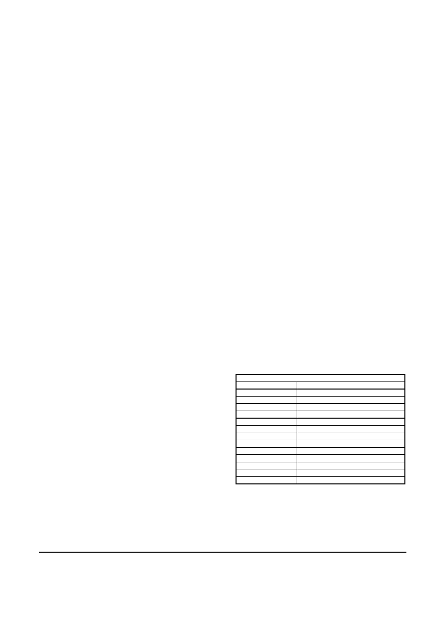
shown in table 5.
Table 5. Suggested component values
Label
Component
R1-R3, R40-R43
22k resistor
R6
1k resistor
R21
470Ω resistor
T1
P-channel Mosfet, e.g. NDS352P
D1-D2
Low Vf switching diode
LED1
Light emitting diode
C1
1μF capacitor
C2, C3
22pF capacitor
C4, C5
27pF capacitor
C6-C7, C9
100nF capacitor
C8
470nF capacitor
X1
12MHz parallel cut crystal
X2
32758Hz parallel cut crystal
In figure 3, the internal memory is used and only
contains components that are strictly necessary. The
device has its own power source Vdd and does not draw
power from the USB port.
Oscillator X1/C2/C3 may be replaced by a low-cost
resonator, provided its frequency tolerance is greater
than 0.25%. C1 and C6 should be placed close to the
相關(guān)PDF資料 |
PDF描述 |
|---|---|
| NCP698SQ13T1G | IC REG LDO 1.3V .28A SC-82AB |
| HMC30DRAH-S734 | CONN EDGECARD 60POS .100 R/A PCB |
| LFXP20E-5F256C | IC FPGA 19.7KLUTS 188I/O 256-BGA |
| LFXP20E-4FN256I | IC FPGA 19.7KLUTS 256FPBGA |
| LFXP20E-4F256I | IC FPGA 19.7KLUTS 188I/O 256-BGA |
相關(guān)代理商/技術(shù)參數(shù) |
參數(shù)描述 |
|---|---|
| USBDESKTOP | 制造商:ETI Systems 功能描述:Joystick;3-Axis;10 Programmable Buttons;Desktop Housing;USB Connector |
| USBDESKTOP-01 | 制造商:ETI Systems 功能描述:Joystick |
| USBDF | 制造商:未知廠家 制造商全稱:未知廠家 功能描述:EMI FILTER AND LINE TERMINATION FOR USB DOWNSTREAM PORTS |
| USBDF01W5 | 功能描述:電磁干擾濾波器 EMI Filter/Line Term RoHS:否 制造商:STMicroelectronics 電容:12 pF 電路類型: 最大直流電流: 最大直流電阻: 電壓額定值:6 V 容差: 端接類型:SMD/SMT 工作溫度范圍:- 30 C to + 85 C 系列:EMIF03 |
| USBDF01W6 | 制造商:STMicroelectronics 功能描述: |
發(fā)布緊急采購,3分鐘左右您將得到回復。