- 您現(xiàn)在的位置:買賣IC網(wǎng) > PDF目錄383983 > UPD72042GT (NEC Corp.) LSI DEVICES FOR Inter Equipment BusTM (IEBusTM) PROTOCOL CONTROL PDF資料下載
參數(shù)資料
| 型號: | UPD72042GT |
| 廠商: | NEC Corp. |
| 英文描述: | LSI DEVICES FOR Inter Equipment BusTM (IEBusTM) PROTOCOL CONTROL |
| 中文描述: | LSI器件間設(shè)備BusTM(IEBusTM)協(xié)議控制 |
| 文件頁數(shù): | 31/92頁 |
| 文件大小: | 373K |
| 代理商: | UPD72042GT |
第1頁第2頁第3頁第4頁第5頁第6頁第7頁第8頁第9頁第10頁第11頁第12頁第13頁第14頁第15頁第16頁第17頁第18頁第19頁第20頁第21頁第22頁第23頁第24頁第25頁第26頁第27頁第28頁第29頁第30頁當(dāng)前第31頁第32頁第33頁第34頁第35頁第36頁第37頁第38頁第39頁第40頁第41頁第42頁第43頁第44頁第45頁第46頁第47頁第48頁第49頁第50頁第51頁第52頁第53頁第54頁第55頁第56頁第57頁第58頁第59頁第60頁第61頁第62頁第63頁第64頁第65頁第66頁第67頁第68頁第69頁第70頁第71頁第72頁第73頁第74頁第75頁第76頁第77頁第78頁第79頁第80頁第81頁第82頁第83頁第84頁第85頁第86頁第87頁第88頁第89頁第90頁第91頁第92頁
μ
PD72042
31
Data Sheet S14870EJ1V0DS00
Cautions 1. In standby mode (with STM of the FLG register set to 1), the user can only write to the CTR
register (including standby mode cancellation) and read from the FLG register.
2. Never access a free address.
3. Slave status (SSR) can be read into RBF by setting the control bits to 0H or 6H from the master
unit.
CTR
Address
Read/write
When reset :
×××
00
××
1B
: 0000B (0H)
: Write
Control register
CTR is a one-byte write register used to control
μ
PD72042 operations.
[REEN]
When REEN is set to 1, the SLRE flag of the FLG register is immediately set to 1 to enable both slave and broadcast
reception.
[SRST]
When SRST is set to 1, the
μ
PD72042 is immediately reset. (Note, however, that STREQ is set to a written value.)
[STREQ]
1: Requests standby mode.
0: Exits from standby mode.
Standby mode setting and cancellation
The
μ
PD72042 is requested to enter the standby mode by setting the STREQ flag to 1 from the microcomputer.
The
μ
PD72042 enters standby mode when the standby mode input enabled state (carrier sense state) is set. In
this case, the impedance of the BUS+ and BUS– pins goes high (logic 1), and the STM flag of the FLG register
is set to 1. In standby mode, oscillation is stopped, and all operations are stopped while preserving the internal
data, thus minimizing power consumption.
When, in standby mode, the STREQ flag is set to 0 from the microcomputer, standby mode is cancelled
after the period (about 20 ms) needed for oscillation to stabilize; the halted operations are resumed from the point
at which standby mode was set. At this time, the STM flag of the FLG register changes to 0.
In standby mode, only writing to the CTR register (for standby mode cancellation) and reading from the FLG register
can be performed from the microcomputer.
Cautions 1. When the SRST flag and STREQ flag are simultaneously set to 1, standby mode is set after
software reset. (This state is the same as that set by hardware reset.) Note, however, that
when the SRST flag is set to 1 in standby mode, a software reset is performed, but this is not
reflected in the FLG register.
2. Do not read any data from internal registers via the serial I/O during the period from when a
microcomputer sets the STREQ flag to 1 to when the
μ
PD72042 enters the standby mode. This
period is one-communication frame at maximum.
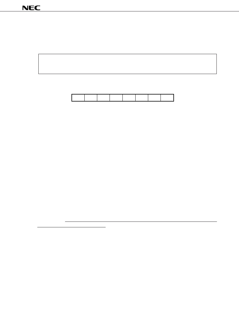
b7
—
b6
—
b5
—
b4
b3
b0
—
CTR
b2
b1
REEN
SRST
—
STREQ
相關(guān)PDF資料 |
PDF描述 |
|---|---|
| uPD72107GC-3B9 | LAP-B CONTROLLER(Link Access Procedure Balanced mode) |
| UPD72107 | LAP-B CONTROLLER(Link Access Procedure Balanced mode) |
| uPD72107CW | LAP-B CONTROLLER(Link Access Procedure Balanced mode) |
| uPD72107L | LAP-B CONTROLLER(Link Access Procedure Balanced mode) |
| UPD75008 | 4-BIT SINGLE-CHIP MICROCOMPUTER |
相關(guān)代理商/技術(shù)參數(shù) |
參數(shù)描述 |
|---|---|
| UPD72042GT(A) | 制造商:Renesas Electronics Corporation 功能描述: |
| UPD720902AF5-667-JF2-E3-A | 功能描述:IC ADVANCED MEMORY BUFFER D1 RoHS:是 類別:集成電路 (IC) >> 接口 - 專用 系列:* 標(biāo)準(zhǔn)包裝:90 系列:- 應(yīng)用:PCI 至 PCI 橋 接口:PCI 電源電壓:3 V ~ 3.6 V 封裝/外殼:257-LFBGA 供應(yīng)商設(shè)備封裝:257-BGA MICROSTAR(16x16) 包裝:托盤 安裝類型:表面貼裝 產(chǎn)品目錄頁面:882 (CN2011-ZH PDF) 其它名稱:296-19316 |
| UPD72255YF1-GA5-A | 制造商:Renesas Electronics Corporation 功能描述: |
| UPD7225G | 制造商:Panasonic Industrial Company 功能描述:IC |
| UPD7225GB-3B7(A) | 制造商:Renesas Electronics Corporation 功能描述: |
發(fā)布緊急采購,3分鐘左右您將得到回復(fù)。