- 您現(xiàn)在的位置:買賣IC網(wǎng) > PDF目錄383976 > UPC1555C (NEC Corp.) TIMER CIRCUIT PDF資料下載
參數(shù)資料
| 型號(hào): | UPC1555C |
| 廠商: | NEC Corp. |
| 英文描述: | TIMER CIRCUIT |
| 中文描述: | 定時(shí)器電路 |
| 文件頁(yè)數(shù): | 2/12頁(yè) |
| 文件大小: | 103K |
| 代理商: | UPC1555C |
2
μ
PC1555
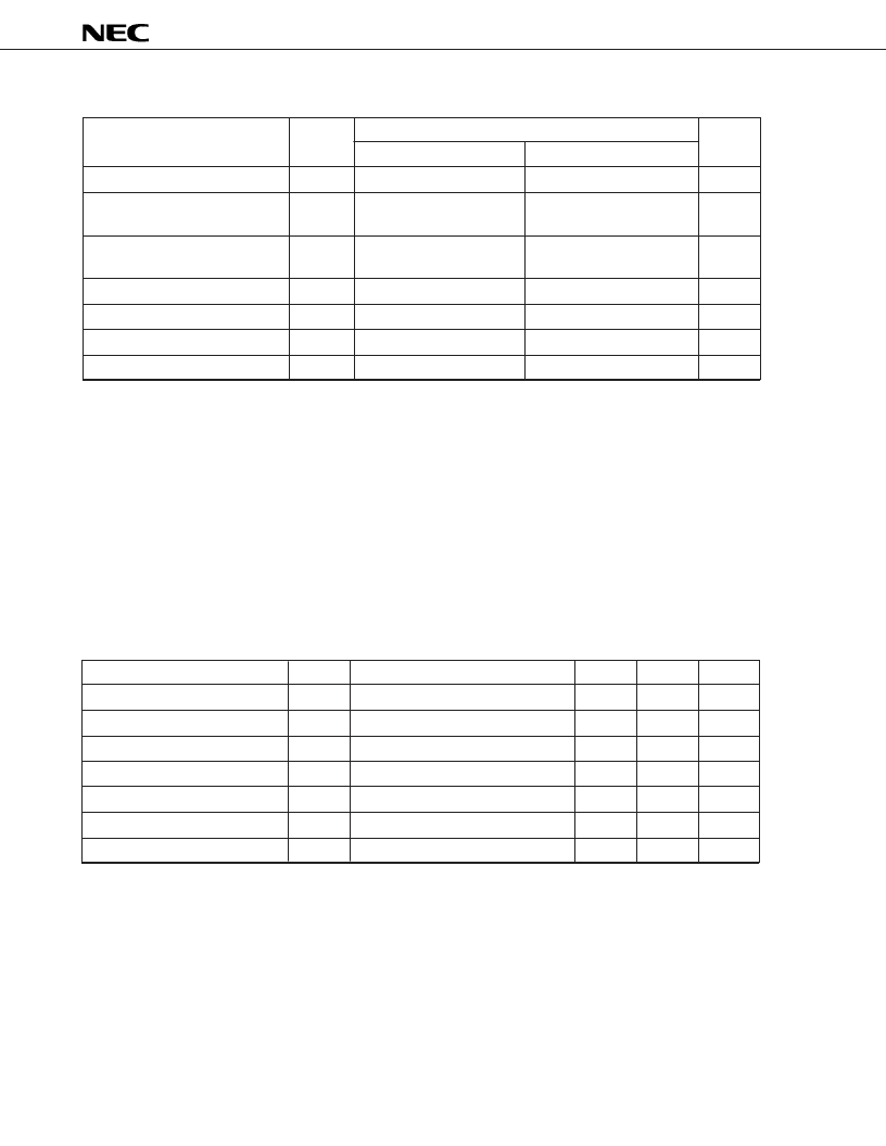
ABSOLUTE MAXIMUM RATINGS
(T
A
= 25
°
C)
Notes 1.
Be sure to use the product within the Power dissipation.
2.
For T
A
≥
25
°
C, the total loss is derated at T
J
MAX
= 125
°
C and –6 mW/
°
C.
(See the P
T
-T
A
characteristic curve.)
3.
For T
A
≥
25
°
C, the total loss is derated at T
J
MAX
= 125
°
C and –4.4 mW/
°
C.
(See the P
T
-T
A
characteristic curve.)
4.
This is an external voltage that can be applied to the output pin without deteriorating the quality of the
product or causing damage to the product.
Be sure to use the product within the rated value under any conditions where coils are inserted or power
is turned on or off. The output voltage that can be obtained during normal operation is within the output
saturation voltage range.
RECOMMENDED OPERATING CONDITIONS
(T
A
= 25
°
C)
Parameter
Symbol
Conditions
MIN.
MAX.
Unit
Supply voltage
V
CC
4.5
16
V
Oscillation frequency
f
V
CC
= 5 to 15 V
0.1
100 k
Hz
Output pulse width
t
W (OUT)
V
CC
= 5 to 15 V
10
μ
10
Sec
Input voltage (trigger, threshold)
V
IN
0
V
CC
V
Input voltage
Note 5
(control)
V
IN
3.0
V
CC
1.5
V
Reset voltage (high level)
V
reset H
V
CC
= 5 to 15 V
1.0
V
CC
V
Reset voltage (low level)
V
reset L
V
CC
= 5 to 15 V
0
0.4
V
Note 5.
This parameter defines the voltage that can be applied when a PWM mode application circuit is
configured by applying an external voltage to the control pin. Usually, a capacitance of 0.01
μ
F is
connected as shown in the application circuit.
Rated value
Parameter
Symbol
μ
PC1555C
μ
PC1555G
Unit
Supply voltage
V
CC
–0.3 to +18
–0.3 to +18
V
Input voltage
(trigger, threshold, reset, control)
V
IN
–0.3 to V
CC
+ 0.3
–0.3 to V
CC
+ 0.3
V
Applicable output voltage
Note 4
(output and discharge)
V
O
–0.3 to V
CC
+ 0.3
–0.3 to V
CC
+ 0.3
V
Output current
I
O
200
Note 1
200
Note 1
mA
Power dissipation
P
T
600
Note 2
440
Note 3
mW
Operating temperature
T
A
–20 to +80
–20 to +80
°
C
Storage temperature
T
stg
–55 to +125
–55 to +125
°
C
相關(guān)PDF資料 |
PDF描述 |
|---|---|
| UPC1555G2 | TIMER CIRCUIT |
| UPC1652G | SILICON MONOLITHIC BIPOLAR INTEGRATED CIRCUIT WIDE BAND AMPLIFIER |
| UPC1654 | 1.0 GHz SILICON MMIC AMPLIFIER |
| UPC1656 | 850 MHz WIDE-BAND SILICON MMIC AMPLIFIER |
| UPC1663G | ULTRA-WIDEBAND DIFFERENTIAL VIDEO AMPLIFIER |
相關(guān)代理商/技術(shù)參數(shù) |
參數(shù)描述 |
|---|---|
| UPC1555C-A | 制造商:Renesas Electronics 功能描述:Bulk |
| UPC1555G2 | 制造商:Renesas Electronics Corporation 功能描述:Semiconductor, Timer, SOP8,Vcc4.5to16V,I |
| UPC1555G2-A | 制造商:Renesas Electronics 功能描述:Cut Tape 制造商:Renesas 功能描述:Standard Timer Single 8-Pin SOP |
| UPC156 | 制造商:未知廠家 制造商全稱:未知廠家 功能描述: |
| UPC156A | 制造商:未知廠家 制造商全稱:未知廠家 功能描述:INDUSTRIAL LINEAR ICS |
發(fā)布緊急采購(gòu),3分鐘左右您將得到回復(fù)。