- 您現(xiàn)在的位置:買賣IC網(wǎng) > PDF目錄98229 > THS8200PFPG4 (TEXAS INSTRUMENTS INC) SPECIALTY CONSUMER CIRCUIT, PQFP80 PDF資料下載
參數(shù)資料
| 型號(hào): | THS8200PFPG4 |
| 廠商: | TEXAS INSTRUMENTS INC |
| 元件分類: | 消費(fèi)家電 |
| 英文描述: | SPECIALTY CONSUMER CIRCUIT, PQFP80 |
| 封裝: | GREEN, PLASTIC, HTQFP-80 |
| 文件頁(yè)數(shù): | 12/101頁(yè) |
| 文件大小: | 806K |
| 代理商: | THS8200PFPG4 |
第1頁(yè)第2頁(yè)第3頁(yè)第4頁(yè)第5頁(yè)第6頁(yè)第7頁(yè)第8頁(yè)第9頁(yè)第10頁(yè)第11頁(yè)當(dāng)前第12頁(yè)第13頁(yè)第14頁(yè)第15頁(yè)第16頁(yè)第17頁(yè)第18頁(yè)第19頁(yè)第20頁(yè)第21頁(yè)第22頁(yè)第23頁(yè)第24頁(yè)第25頁(yè)第26頁(yè)第27頁(yè)第28頁(yè)第29頁(yè)第30頁(yè)第31頁(yè)第32頁(yè)第33頁(yè)第34頁(yè)第35頁(yè)第36頁(yè)第37頁(yè)第38頁(yè)第39頁(yè)第40頁(yè)第41頁(yè)第42頁(yè)第43頁(yè)第44頁(yè)第45頁(yè)第46頁(yè)第47頁(yè)第48頁(yè)第49頁(yè)第50頁(yè)第51頁(yè)第52頁(yè)第53頁(yè)第54頁(yè)第55頁(yè)第56頁(yè)第57頁(yè)第58頁(yè)第59頁(yè)第60頁(yè)第61頁(yè)第62頁(yè)第63頁(yè)第64頁(yè)第65頁(yè)第66頁(yè)第67頁(yè)第68頁(yè)第69頁(yè)第70頁(yè)第71頁(yè)第72頁(yè)第73頁(yè)第74頁(yè)第75頁(yè)第76頁(yè)第77頁(yè)第78頁(yè)第79頁(yè)第80頁(yè)第81頁(yè)第82頁(yè)第83頁(yè)第84頁(yè)第85頁(yè)第86頁(yè)第87頁(yè)第88頁(yè)第89頁(yè)第90頁(yè)第91頁(yè)第92頁(yè)第93頁(yè)第94頁(yè)第95頁(yè)第96頁(yè)第97頁(yè)第98頁(yè)第99頁(yè)第100頁(yè)第101頁(yè)

4–3
Y7(0)
Y6(0)
Y5(0)
Y4(0)
Y3(0)
Y2(0)
Y1(0)
Y7(1)
Y6(1)
Y5(1)
Y4(1)
Y3(1)
Y2(1)
Y1(1)
Y7(2)
Y6(2)
Y5(2)
Y4(2)
Y3(2)
Y2(2)
Y1(2)
Y7(3)
Y6(3)
Y5(3)
Y4(3)
Y3(3)
Y2(3)
Y1(3)
GY[9]
GY[8]
GY[7]
GY[6]
GY[5]
GY[4]
GY[3]
GY[2]
Cb7(0)
Cb6(0)
Cb5(0)
Cb4(0)
Cb3(0)
Cb2(0)
Cb1(0)
Cb0(0)
Cr7(0)
Cr6(0)
Cr5(0)
Cr4(0)
Cr3(0)
Cr2(0)
Cr1(0)
Cr0(0)
Cb7(2)
Cb6(2)
Cb5(2)
Cb4(2)
Cb3(2)
Cb2(2)
Cb1(2)
Cb0(2)
Cr7(2)
Cr6(2)
Cr5(2)
Cr4(2)
Cr3(2)
Cr2(2)
Cr1(2)
Cr0(2)
BCb[9]
BCb[8]
BCb[7]
BCb[6]
BCb[5]
BCb[4]
BCb[3]
BCb[2]
X
RCr[9]
RCr[8]
RCr[7]
RCr[6]
RCr[5]
RCr[4]
RCr[3]
RCr[2]
CLKIN
Data
Manager
Cb7(0)
Cb6(0)
Cb5(0)
Cb4(0)
Cb3(0)
Cb7(2)
Cb6(2)
Cb5(2)
Cb4(2)
Cb3(2)
TO CH1
TO CH2
TO CH3
Y7(0)
Y6(0)
Y5(0)
Y4(0)
Y3(0)
Y2(0)
Y1(0)
Y6(1)
Y7(2)
Y6(2)
Y5(2)
Y4(2)
Y3(2)
Y2(2)
Y1(2)
Y7(3)
Y6(3)
Y5(3)
Y4(3)
Y3(3)
Y2(3)
Y1(3)
Cb2(0)
Cb1(0)
Cb0(0)
Cb2(2)
Cb1(2)
Cb0(2)
Cr7’(1)
Cr7(2)
Cr6(2)
Cr5(2)
Cr4(2)
Cr3(2)
Cr6’(1)
Cr5’(1)
Cr4’(1)
Cr3’(1)
Cr2’(1)
Cr1’(0)
Cr0’(1)
Cr2(2)
Cr1(2)
Cr0(2)
Cr7(0)
Cr6(0)
Cr5(0)
Cr4(0)
Cr3(0)
Cr2(0)
Cr1(0)
Cr0(0)
Cr7’(3)
Cr6’(3)
Cr5’(3)
Cr4’(3)
Cr3’(3)
Cr2’(3)
Cr1’(3)
Cr0’(3)
Y7(1)
Y5(1)
Y4(1)
Y3(1)
Y2(1)
Y1(1)
Cb7’(1)
Cb5’(1)
Cb4’(1)
Cb3’(1)
Cb2’(1)
Cb1’(1)
Cb0’(1)
Cb6’(1)
Cb7’(3)
Cb6’(3)
Cb5’(3)
Cb4’(3)
Cb3’(3)
Cb2’(3)
Cb1’(3)
Cb0’(3)
NOTE: Where Cb’Cr’ are the output of half-band interpolation filter.
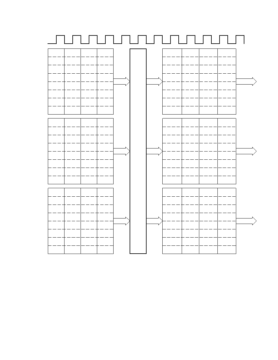
Figure 4–2. 20-/16-Bit YCbCr 4:2:2 Data Format (16-Bit Operation Shown)
When dedicated timing is used in this mode, there is a fixed relationship between the first active period of HS_IN (i.e.,
the first CLKIN rising edge seeing HS_IN active) and a Cb color component assumed present during that clock period
on the bus receiving CbCr samples. When embedded timing is used in this mode, the SAV/EAV structure also
unambiguously defines the CbCr sequence, according to SMPTE274M/296M for HDTV.
NOTE: The figure shows the case when only 8 bits of each 10-bit input bus are used.
10-bit YCbCr 4:2:2 (ITU mode)
CLKIN is equal to 2
× the pixel clock since all components are multiplexed on a single 10-bit bus with a 4-multiple
sequence: CbYCrY. Therefore the pixel clock (i.e., the Y input rate) is 1/2 of CLKIN and the Cb and Cr rate are 1/4
of CLKIN.
相關(guān)PDF資料 |
PDF描述 |
|---|---|
| THS8210PFP | SPECIALTY CONSUMER CIRCUIT, PQFP80 |
| TK10840MCBX | FM, AUDIO DEMODULATOR, PDSO20 |
| TK10840MCMG | FM, AUDIO DEMODULATOR, PDSO20 |
| TK10840MCTL | FM, AUDIO DEMODULATOR, PDSO20 |
| TK10840MCTR | FM, AUDIO DEMODULATOR, PDSO20 |
相關(guān)代理商/技術(shù)參數(shù) |
參數(shù)描述 |
|---|---|
| THS8-38R-D | 制造商:Thomas & Betts 功能描述:HEAT SHRINK RING 8AWG 3/8 STUD 制造商:Thomas & Betts 功能描述:CATAMOUNT CABLE TIES |
| THS8-516R-D | 制造商:Thomas & Betts 功能描述:CATAMOUNT CABLE TIES |
| THS8-BS-W | 制造商:Thomas & Betts 功能描述:HEAT SHRINK BUTT SPLICE 8AWG |
| THS9 | 制造商:Apex Tool Group 功能描述:HS-9 9/32 HEX NUTDRIVER |
| THS9000 | 制造商:TI 制造商全稱:Texas Instruments 功能描述:50 MHz to 400 MHz CASCADEABLE AMPLIFIER |
發(fā)布緊急采購(gòu),3分鐘左右您將得到回復(fù)。