- 您現(xiàn)在的位置:買賣IC網(wǎng) > PDF目錄383943 > TEA1098AH (NXP Semiconductors N.V.) Speech and handsfree IC PDF資料下載
參數(shù)資料
| 型號(hào): | TEA1098AH |
| 廠商: | NXP Semiconductors N.V. |
| 英文描述: | Speech and handsfree IC |
| 中文描述: | 免提語(yǔ)音和集成電路 |
| 文件頁(yè)數(shù): | 7/40頁(yè) |
| 文件大小: | 185K |
| 代理商: | TEA1098AH |
第1頁(yè)第2頁(yè)第3頁(yè)第4頁(yè)第5頁(yè)第6頁(yè)當(dāng)前第7頁(yè)第8頁(yè)第9頁(yè)第10頁(yè)第11頁(yè)第12頁(yè)第13頁(yè)第14頁(yè)第15頁(yè)第16頁(yè)第17頁(yè)第18頁(yè)第19頁(yè)第20頁(yè)第21頁(yè)第22頁(yè)第23頁(yè)第24頁(yè)第25頁(yè)第26頁(yè)第27頁(yè)第28頁(yè)第29頁(yè)第30頁(yè)第31頁(yè)第32頁(yè)第33頁(yè)第34頁(yè)第35頁(yè)第36頁(yè)第37頁(yè)第38頁(yè)第39頁(yè)第40頁(yè)
2000 Mar 21
7
Philips Semiconductors
Preliminary specification
Speech and handsfree IC
TEA1098A
handbook, full pagewidth
1
2
3
4
5
6
7
8
9
10
11
33
32
31
30
29
28
27
26
25
24
23
1
1
1
1
1
1
1
1
2
2
2
4
4
4
4
4
3
3
3
3
3
3
TEA1098AH
FCA142
EARO
DTMF
MIC
+
MIC
TXI
GATX
TXO
IDT
SWT
n.c.
HFRX
TNOI
TENV
TSEN
RNOI
RSEN
DLC
n.c.
GALS
GNDTX
n
L
E
B
M
P
H
R
G
n
H
G
S
L
R
I
A
M
S
S
L
V
RENV
VBB
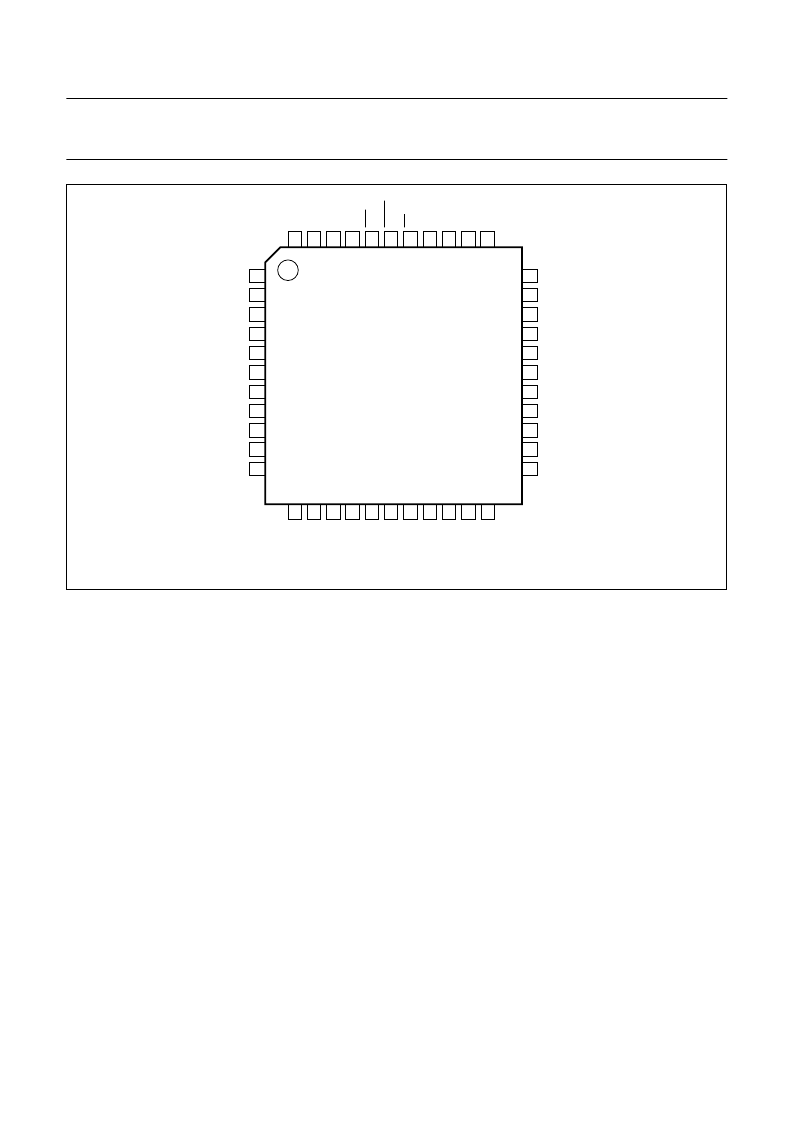
Fig.3 Pin configuration (TEA1098AH).
FUNCTIONAL DESCRIPTION
All data given in this chapter are typical values, except
when otherwise specified.
Supplies
L
INE INTERFACE AND INTERNAL SUPPLY
(
PINS
LN, SLPE,
REG
AND
V
BB
)
The supply for the TEA1098A and its peripherals is
obtained from the line. The IC generates a stabilized
reference voltage (V
ref
) between pins SLPE and GND.
This reference voltage is equal to 3.7 V for line currents
lower than 18 mA. It than increases linearly with the line
current and reaches the value of 6.1 V for line currents
higher than 45 mA. For line currents below 9 mA, the
internal reference voltage generating V
ref
is automatically
adjusted to a lower value. This is the so-called low voltage
area and the TEA1098A has limited performances in this
area (see Section “Low voltage behaviour”). This
reference voltage is temperature compensated.
The voltage between pins SLPE and REG is used by the
internal regulator to generate the stabilized reference
voltageandisdecoupledbymeansofacapacitor between
pins LN and REG.
This capacitor converted into an equivalent inductance
realizes the set impedance conversion from its DC value
(R
SLPE
) to its AC value (done by an external impedance).
The IC regulates the line voltage at pin LN and can be
calculated as follows:
where:
I
line
= line current
I
x
= current consumed on pin LN (approximately a few
μ
A)
I
SLPE
= current flowing through the R
SLPE
resistor
The preferred value for R
SLPE
is 20
. Changing this value
will affect more than the DC characteristics; it also
influences the transmit gains to the line, the gain control
characteristic, the sidetone level and the maximum output
swing on the line.
V
LN
V
ref
R
SLPE
I
×
+
SLPE
=
I
SLPE
I
line
I
x
–
=
相關(guān)PDF資料 |
PDF描述 |
|---|---|
| TEA1098ATV | Speech and handsfree IC |
| TEA1507 | GreenChipII SMPS control IC |
| TEA1507P | GreenChipII SMPS control IC |
| TEA1533P | GreenChip SMPS control IC |
| TEA1533T | GreenChipTMII SMPS control IC |
相關(guān)代理商/技術(shù)參數(shù) |
參數(shù)描述 |
|---|---|
| TEA1098ATV | 制造商:PHILIPS 制造商全稱:NXP Semiconductors 功能描述:Speech and handsfree IC |
| TEA1098H | 制造商:PHILIPS 制造商全稱:NXP Semiconductors 功能描述:Speech and handsfree IC |
| TEA1098TV | 制造商:PHILIPS 制造商全稱:NXP Semiconductors 功能描述:Speech and handsfree IC |
| TEA1098UH | 制造商:PHILIPS 制造商全稱:NXP Semiconductors 功能描述:Speech and handsfree IC |
| TEA1099 | 制造商:PHILIPS 制造商全稱:NXP Semiconductors 功能描述:Speech and handsfree IC with auxiliary inputs/outputs and analog multiplexer |
發(fā)布緊急采購(gòu),3分鐘左右您將得到回復(fù)。