- 您現(xiàn)在的位置:買賣IC網(wǎng) > PDF目錄383844 > STPCD01 STPC CLIENT DATASHEET / PC COMPATIBLE EMBEDED MICROPROCESSOR PDF資料下載
參數(shù)資料
| 型號: | STPCD01 |
| 英文描述: | STPC CLIENT DATASHEET / PC COMPATIBLE EMBEDED MICROPROCESSOR |
| 中文描述: | STPC客戶部件/ PC兼容的嵌入式微處理器 |
| 文件頁數(shù): | 30/61頁 |
| 文件大小: | 1007K |
| 代理商: | STPCD01 |
第1頁第2頁第3頁第4頁第5頁第6頁第7頁第8頁第9頁第10頁第11頁第12頁第13頁第14頁第15頁第16頁第17頁第18頁第19頁第20頁第21頁第22頁第23頁第24頁第25頁第26頁第27頁第28頁第29頁當(dāng)前第30頁第31頁第32頁第33頁第34頁第35頁第36頁第37頁第38頁第39頁第40頁第41頁第42頁第43頁第44頁第45頁第46頁第47頁第48頁第49頁第50頁第51頁第52頁第53頁第54頁第55頁第56頁第57頁第58頁第59頁第60頁第61頁
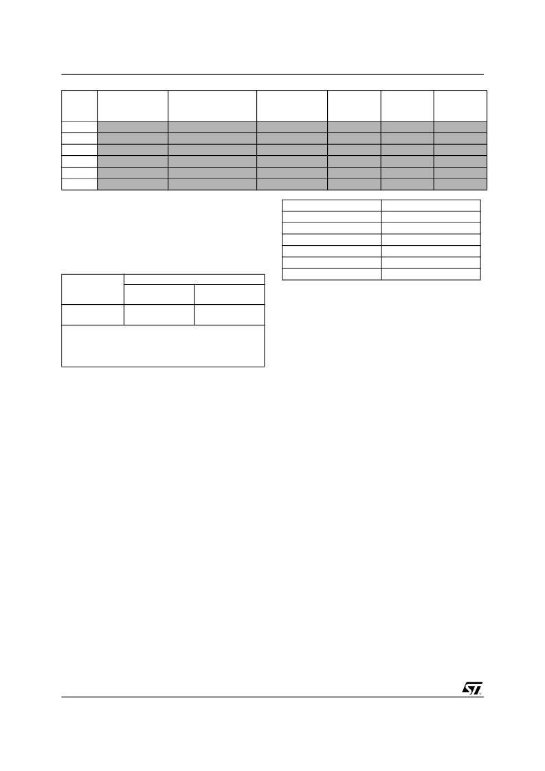
STRAP OPTION
30/61
Issue 2.2 - October 13, 2000
Note 1; Setting of Strap Options MD [15:2] have
no effect on the DRAM Controller but are purely
meant for software issues. i.e. Readable in a reg-
ister.
Note 2; The settings for these Straps is show in
the table below:
For further details refer to Application Note 1297
3.1 Power on strap registers description
3.1.1 Strap register 0 Index 4Ah (Strap0)
Bits 7-0; This register reflect the status of pins
MD[7:0] respectively. They are expected to be
connected on the system board to the SIMM con-
figuration pins as follows:
Note that the SIMM speed and type information
read here is meant only for the software and is not
used by the hardware. The software must pro-
gram the Host and graphics dram controller con-
figuration registers appropriately based on these
bits.
This register defaults to the values sampled on
MD[7:0] pins after reset.
3.1.2 Strap register 1 Index 4Bh (Strap1)
Bits 7-0; This register reflect the status of pins
MD[15:8] respectively. They are expected to be
connected on the system board to the SIMM con-
figuration pins as follows:
MD38
MD39
MD40
MD41
MD42
MD43
-
-
-
-
-
-
Reserved
Reserved
Reserved
Reserved
Reserved
Reserved
-
-
-
-
-
-
-
-
-
-
-
-
-
-
-
-
-
-
-
-
-
-
-
-
Memory
Data
Lines
Refer to
Designation
Location
Actual
Settings
Set to ’0’
Set to ’1’
Strap Option
Devices Settings
MDBT*70xxxx
1
(Old)
Pull Up (1)
Pull Up (1)
MDBT*710Axx
(New)
Pull Down (0)
Pull Down (0)
MD [32]
MD[35]
Note 1; All devices with the exception of the technical
codes; MDBT*S710A
The Devices are identified using the techical code
which is the first line laser marked under the ST logo.
Bit Sampled
Bit 7
Bits 6-5
Bit 4
Bits 3-2
Bit 1
Bit 0
Description
SIMM 0 DRAM type
SIMM 0 speed
SIMM 1 DRAM type:
SIMM 1 speed
Reserved
Reserved
相關(guān)PDF資料 |
PDF描述 |
|---|---|
| STPCD0110BTC3 | 32-Bit Microprocessor |
| STPCD0112BTC3 | 32-Bit Microprocessor |
| STPCD0113BTC3 | 32-Bit Microprocessor |
| STPCI01 | STPC INDUSTRIAL / PC COMPATIBLE EMBEDED MICROPROCESSOR |
| STPCI2 | STPC ATLAS DATASHEET / X86 CORE PC COMPATIBLE SYSTEM-ON-CHIP FOR TERMINALS |
相關(guān)代理商/技術(shù)參數(shù) |
參數(shù)描述 |
|---|---|
| STPCD0110BTC3 | 制造商:未知廠家 制造商全稱:未知廠家 功能描述:32-Bit Microprocessor |
| STPCD0112BTC3 | 制造商:未知廠家 制造商全稱:未知廠家 功能描述:32-Bit Microprocessor |
| STPCD0113BTC3 | 制造商:未知廠家 制造商全稱:未知廠家 功能描述:32-Bit Microprocessor |
| STPCD0166BTA3 | 制造商:STMICROELECTRONICS 制造商全稱:STMicroelectronics 功能描述:PC Compatible Embedded Microprocessor |
| STPCD0166BTC3 | 制造商:STMicroelectronics 功能描述:MPU STPC RISC 64-Bit 66MHz 388-Pin BGA |
發(fā)布緊急采購,3分鐘左右您將得到回復(fù)。