- 您現在的位置:買賣IC網 > PDF目錄372115 > SAA7370A (NXP SEMICONDUCTORS) Digital servo processor and Compact Disc decoder CD7 PDF資料下載
參數資料
| 型號: | SAA7370A |
| 廠商: | NXP SEMICONDUCTORS |
| 元件分類: | 消費家電 |
| 英文描述: | Digital servo processor and Compact Disc decoder CD7 |
| 中文描述: | SPECIALTY CONSUMER CIRCUIT, PQFP64 |
| 封裝: | 14 X 14 MM, 2.70 MM HEIGHT, PLASTIC, MS-022, SOT-393-1, QFP-64 |
| 文件頁數: | 29/60頁 |
| 文件大?。?/td> | 248K |
| 代理商: | SAA7370A |
第1頁第2頁第3頁第4頁第5頁第6頁第7頁第8頁第9頁第10頁第11頁第12頁第13頁第14頁第15頁第16頁第17頁第18頁第19頁第20頁第21頁第22頁第23頁第24頁第25頁第26頁第27頁第28頁當前第29頁第30頁第31頁第32頁第33頁第34頁第35頁第36頁第37頁第38頁第39頁第40頁第41頁第42頁第43頁第44頁第45頁第46頁第47頁第48頁第49頁第50頁第51頁第52頁第53頁第54頁第55頁第56頁第57頁第58頁第59頁第60頁
1998 Feb 26
29
Philips Semiconductors
Product specification
Digital servo processor and Compact Disc
decoder (CD7)
SAA7370A
7.14.8.4
Automatic sequencers and timer interrupts
Two automatic sequencers are implemented (and must be
initialized after power-on);
1.
Autostart sequencer: controls the start-up of focus,
radial and motor.
2.
Autostop sequencer: brakes the disc and shuts down
servos.
When the automatic sequencers are not used it is possible
to generate timer interrupts, defined by the
time_parameter coefficient.
7.14.8.5
High-level status
The read high-level status command can be used to obtain
the interrupt, decoder, autosequencer status registers and
the motor start time. Use of the read high-level status
command clears the interrupt status register, and
re-enables the subcode read via a servo command.
7.14.9
D
RIVER INTERFACE
The control signals (pins RA, FO and SL) for the
mechanism actuators are pulse density modulated.
The modulating frequency can be set to either 1.0584 MHz
(DSD mode) or 2.1168 MHz; controlled via the xtra_preset
parameter (it should be noted that these frequencies are
doubled if a 16.9344 MHz crystal is used with
SELPLL = 1). An analog representation of the output
signals can be achieved by connecting a first-order
low-pass filter to the outputs.
During reset (i.e. RESET pin is held LOW) the RA, FO and
SL pins are high-impedance.
7.14.10 L
ASER INTERFACE
The LDON pin (open-drain output) is used to switch the
laser off and on. When the laser is on the output is
high-impedance. The action of the LDON pin is controlled
by the xtra_preset parameter; the pin is automatically
driven if the focus control loop is active.
7.14.11 R
ADIAL SHOCK DETECTOR
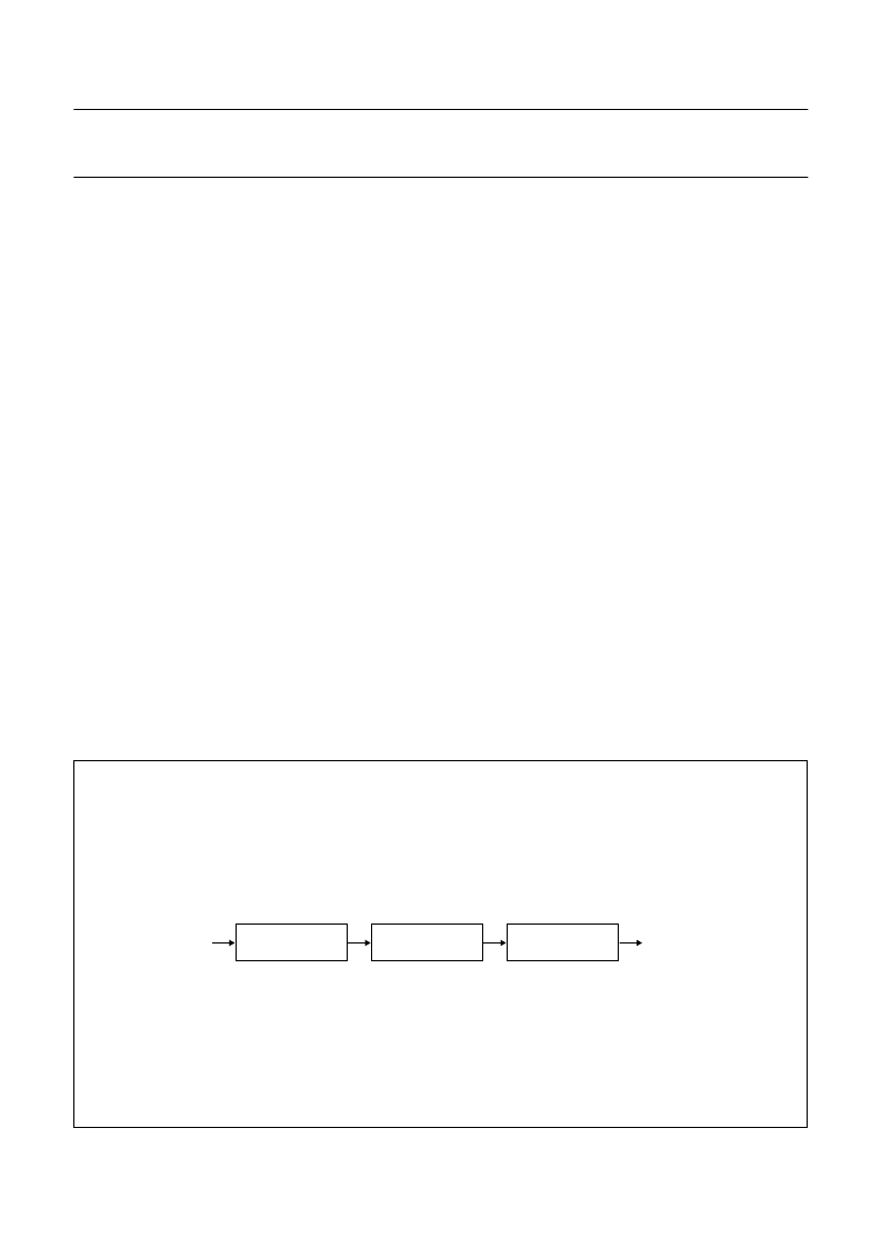
The shock detector (see Fig.21) can be switched on during
normal track following, and detects within an adjustable
frequency whether disturbances in the radial spot position
relative to the track exceed an adjustable level (controlled
by shock_level). Every time the radial tracking error (RE)
exceeds this level the radial control bandwidth is switched
to twice its original bandwidth and the loop gain is
increased by a factor of 4.
The shock detection level is adjustable in 16 steps from
0 to 100% of the traverse radial amplitude which is sent to
an amplitude detection unit via an adjustable band-pass
filter (controlled by sledge_parm1); lower corner frequency
can be set at either 0 or 20 Hz, and upper corner
frequency at 750 or 1850 Hz. The shock detector is
switched off automatically during jump mode.
Fig.21 Block diagram of radial shock detector.
handbook, full pagewidth
RE
MGC914
SHOCK
OUTPUT
HIGH-PASS FILTER
(0 or 20 Hz)
LOW-PASS FILTER
(750 or 1850 Hz)
AMPLITUDE
DETECTION
相關PDF資料 |
PDF描述 |
|---|---|
| SAA7370 | Digital servo processor and Compact Disc decoder CD7 |
| SAA7371 | Digital servo processor and Compact Disc decoder CD7 |
| SAA7371GP | Digital servo processor and Compact Disc decoder CD7 |
| SAA7372 | Digital servo processor and Compact Disc decoder CD7 |
| SAA7373 | Digital servo processor and Compact Disc decoder CD7 |
相關代理商/技術參數 |
參數描述 |
|---|---|
| SAA7371 | 制造商:PHILIPS 制造商全稱:NXP Semiconductors 功能描述:Digital servo processor and Compact Disc decoder CD7 |
| SAA7371GP | 制造商:PHILIPS 制造商全稱:NXP Semiconductors 功能描述:Digital servo processor and Compact Disc decoder CD7 |
| SAA7372 | 制造商:PHILIPS 制造商全稱:NXP Semiconductors 功能描述:Digital servo processor and Compact Disc decoder CD7 |
| SAA7373 | 制造商:PHILIPS 制造商全稱:NXP Semiconductors 功能描述:Digital servo processor and Compact Disc decoder CD7 |
| SAA7373GP | 制造商:PHILIPS 制造商全稱:NXP Semiconductors 功能描述:Digital servo processor and Compact Disc decoder CD7 |
發(fā)布緊急采購,3分鐘左右您將得到回復。