- 您現(xiàn)在的位置:買賣IC網(wǎng) > PDF目錄98068 > S1C60L05D 4-BIT, MROM, 0.08 MHz, MICROCONTROLLER, UUC53 PDF資料下載
參數(shù)資料
| 型號(hào): | S1C60L05D |
| 元件分類: | 微控制器/微處理器 |
| 英文描述: | 4-BIT, MROM, 0.08 MHz, MICROCONTROLLER, UUC53 |
| 封裝: | DIE-53 |
| 文件頁數(shù): | 57/104頁 |
| 文件大小: | 697K |
| 代理商: | S1C60L05D |
第1頁第2頁第3頁第4頁第5頁第6頁第7頁第8頁第9頁第10頁第11頁第12頁第13頁第14頁第15頁第16頁第17頁第18頁第19頁第20頁第21頁第22頁第23頁第24頁第25頁第26頁第27頁第28頁第29頁第30頁第31頁第32頁第33頁第34頁第35頁第36頁第37頁第38頁第39頁第40頁第41頁第42頁第43頁第44頁第45頁第46頁第47頁第48頁第49頁第50頁第51頁第52頁第53頁第54頁第55頁第56頁當(dāng)前第57頁第58頁第59頁第60頁第61頁第62頁第63頁第64頁第65頁第66頁第67頁第68頁第69頁第70頁第71頁第72頁第73頁第74頁第75頁第76頁第77頁第78頁第79頁第80頁第81頁第82頁第83頁第84頁第85頁第86頁第87頁第88頁第89頁第90頁第91頁第92頁第93頁第94頁第95頁第96頁第97頁第98頁第99頁第100頁第101頁第102頁第103頁第104頁
48
EPSON
S1C60N05 TECHNICAL MANUAL
CHAPTER 4: PERIPHERAL CIRCUITS AND OPERATION (A/D Converter)
(3) Counter
The A/D converter incorporates two types of 16-bit
counters. One is the up-counter C0–C15 that counts the
aforementioned oscillation clock, and the other is up/
down counter TC0–TC15 that counts the internal clock
for reference counting. Each counter permits reading and
writing on a 4-bit basis.
The input unit of the up/down counter TC0–TC15 incor-
porates a multiplying circuit so that either the OSC1
clock (Typ. 32.768 kHz) or its multiplication clock (Typ.
65.536 kHz) can be selected as an input clock.
When A/D conversion is initiated by the ADRUN register,
oscillation by the reference resistance begins first, and
the up-counter C0–C15 starts counting up according to
the oscillation clock. At the same time, the up/down
counter TC0–TC15 starts counting up.
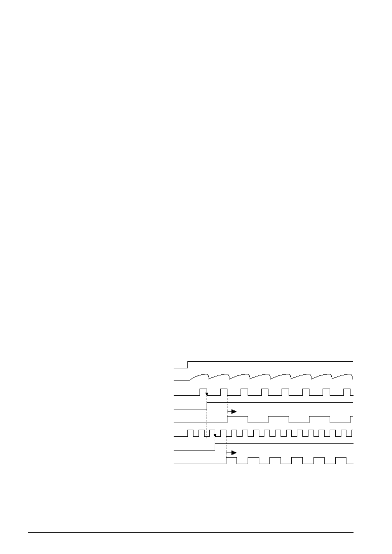
Timing in starting oscillation and starting counting up
are shown in Figure 4.8.3.
The up-counter becomes ENABLE at the falling edge of
the first clock after CR oscillation is initiated and starts
counting up from the falling edge of the next clock.
The up/down counter becomes ENABLE at the falling
edge of the internal clock which is input immediately
after the first CR oscillation clock has fallen. Then, it
starts counting up from the falling edge of the next inter-
nal clock.
Fig. 4.8.3
Counting up start
timing
ADRUN register
CS terminal
ADOUT
Up-counter enable
Up-counter (C0)
Clock (Up/down counter)
Up/down counter enable
Up/down counter (TC0)
Start
If the up-counter C0–C15 becomes "0000H" due to over-
flow, the sensor side of the oscillation circuit turns on,
and the up-counter starts counting up according to the
oscillation clock on the sensor side.
相關(guān)PDF資料 |
PDF描述 |
|---|---|
| S1C60L13F | 4-BIT, MROM, 0.032768 MHz, MICROCONTROLLER, PQFP80 |
| S1C60L13D | 4-BIT, MROM, 0.032768 MHz, MICROCONTROLLER, UUC79 |
| S1C60A13F | 4-BIT, MROM, 1.2 MHz, MICROCONTROLLER, PQFP80 |
| S1C60L16F0A0100 | 4-BIT, MROM, 0.032768 MHz, MICROCONTROLLER, PQFP80 |
| S1C60N01F | 4-BIT, MROM, 0.08 MHz, MICROCONTROLLER, PQFP48 |
相關(guān)代理商/技術(shù)參數(shù) |
參數(shù)描述 |
|---|---|
| S1C60L08 | 制造商:EPSON 制造商全稱:EPSON 功能描述:4-bit Single Chip Microcomputer |
| S1C60L16 | 制造商:EPSON 制造商全稱:EPSON 功能描述:4-bit Single Chip Microcomputer |
| S1C60N05 | 制造商:EPSON 制造商全稱:EPSON 功能描述:4-bit Single Chip Microcomputer |
| S1C60N08 | 制造商:EPSON 制造商全稱:EPSON 功能描述:4-bit Single Chip Microcomputer |
| S1C60N16 | 制造商:EPSON 制造商全稱:EPSON 功能描述:4-bit Single Chip Microcomputer |
發(fā)布緊急采購,3分鐘左右您將得到回復(fù)。