- 您現(xiàn)在的位置:買賣IC網(wǎng) > PDF目錄192282 > S1006FS31 6 A, 100 V, SCR, TO-220AB PDF資料下載
參數(shù)資料
| 型號: | S1006FS31 |
| 元件分類: | 晶閘管 |
| 英文描述: | 6 A, 100 V, SCR, TO-220AB |
| 封裝: | TO-220AB, 3 PIN |
| 文件頁數(shù): | 7/12頁 |
| 文件大?。?/td> | 188K |
| 代理商: | S1006FS31 |
Electrical Specifications
Sensitive SCRs
5-4
Teccor Electronics, Inc.
(972) 580-7777
General Notes
Teccor 2N5060 and 2N6564 Series devices conform to all JEDEC
registered data. See specifications table on page 5-2.
The case temperature (TC) is measured as shown on dimensional
outline drawings. See “Package Dimensions” section of this
catalog.
All measurements (except IGT) are made with an external resistor
RGK = 1k unless otherwise noted.
All measurements are made at 60Hz with a resistive load at an
ambient temperature of +25oC unless otherwise specified.
Operating temperature (TJ) is -65
oC to + 110oC for “EC” Series
devices; -65oC to +125oC for “2N” Series devices; -40oC to +125oC
for “TCR” Series; and -40
oC to +110oC for all others.
Storage temperature range (TS) is -65
oC to + 150oC for TO-92
devices; -40
oC to +150oC for TO-202 devices; and -40oC to
+125oC for all others.
Lead solder temperature is a maximum of +230oC for 10 seconds
maximum
≥ 1/16" (1.59mm) from case.
Electrical Specification Notes
(1)
See Figures 5.1 through 5.9 for current ratings at specified operat-
ing case temperatures.
(2)
See Figure 5.10 for IGT vs TC.
(3)
See Figure 5.11 for instantaneous on-state current (iT) vs on-state
voltage (vT) - (typical).
(4)
See Figure 5.12 for VGT vs TC.
(5)
See Figure 5.13 for IH vs TC.
(6)
For more than one full cycle, see Figure 5.14.
(7)
0.8 - 4.0A devices also have a pulse peak forward current on-state
rating (repetitive) of 75A. This rating applies for operation at 60Hz,
75°C maximum tab (or anode) lead temperature, switching from
80V peak, sinusoidal current pulse width of 10
s minimum, 15s
maximum. See Figures 5.20 and 5.21.
(8)
See Figure 5.15 for tgt vs IGT.
(9)
Test conditions as follows:
TC ≤ 80°C, rectangular current waveform; rate-of-rise of current
≤ 10A/s. Rate-of-reversal of current ≤ 5A/s. ITM = 1A (50s
pulse) Repetition Rate = 60pps. VRRM = Rated. VR = 15V mini-
mum, VDRM = Rated. Rate-of-rise reapplied forward blocking volt-
age = 5V/
s. Gate Bias = 0V, 100 (during turn-off time interval).
(10) Test condition is maximum rated RMS current except TO-92
devices are 1.2APK; T106/T107 devices are 4APK.
(11) VD = 6VDC, RL = 100. See Figure 5.19 for simple test circuit for
measuring gate trigger voltage and gate trigger current.
(12) See Figures 5.1 through 5.9 for maximum allowable case temper-
ature at maximum rated current.
(13) IGT = 500A maximum for TC = -40°C for T106 devices.
(14) IH = 10mA maximum for TC = -65°C for 2N5060 Series and
2N6564 Series devices.
(15) IH = 6mA maximum for TC = -40°C for T106 devices.
(16) Pulse Width
≤ 10s.
(17) IGT = 350A maximum at TC = -65°C for 2N5060 Series and
2N6564 Series devices.
(18) Latching current can be higher than 20mA for higher IGT types.
Also latching current can be much higher at -40°C. See Figure
5.18.
(19) TC = TJ for test conditions in off-state.
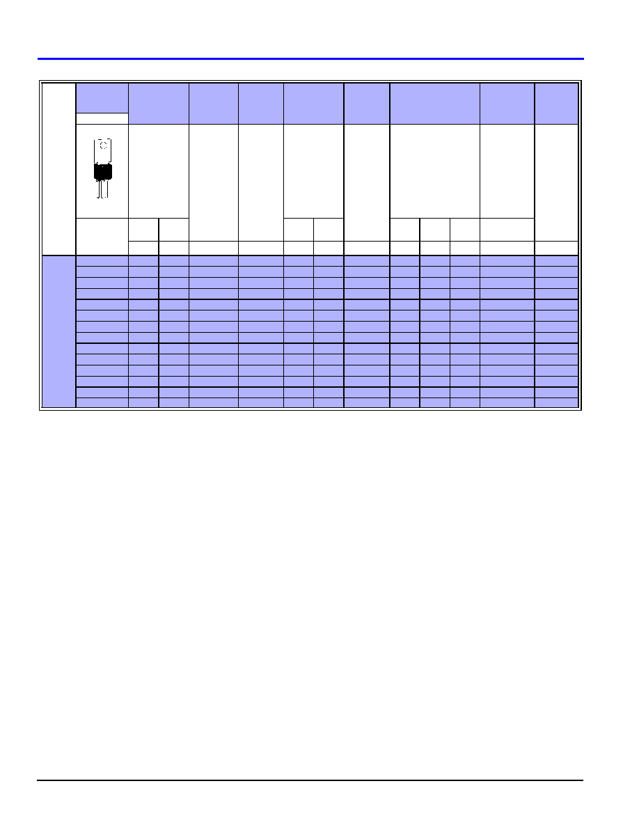
TYPE
Part
Number
IT
VDRM &
VRRM
IGT
IDRM &
IRRM
VTM
VGT
IH
IGM
Non-Isolated
TO-202AB
Maximum
On-State
Current
(1)
Amps
Repetitive
Peak
Off-State
Forward &
Reverse
Voltage
Volts
DC Gate
Trigger
Current
(2) (11) (13)
Amps
Peak Off-State
Current at
VDRM & VRRM
(19)
Amps
Peak
On-State
Voltage
TC = 25°C
(3) (10)
Volts
DC Gate
Trigger Voltage
(4) (11)
Volts
DC Holding
Current
Initial On-State
Current = 20mA
(5) (15) (18)
mAmps
Peak Gate
Current
(16)
Amps
See “Package
Dimensions”
section for
variations.
IT(RMS)
IT(AV)
TC =
25°C
TC =
110°C
TC =
- 40°C
TC =
25°C
TC =
110°C
TC = 25°C
MAX
MIN
MAX
MIN
MAX
4.0
Amps
T106F1
4.0
2.5
50
200
2.0
100
2.2
1.0
0.8
0.2
5.0
1.0
T106A1
4.0
2.5
100
200
2.0
100
2.2
1.0
0.8
0.2
5.0
1.0
T106B1
4.0
2.5
200
2.0
100
2.2
1.0
0.8
0.2
5.0
1.0
T106C1
4.0
2.5
300
200
2.0
100
2.2
1.0
0.8
0.2
5.0
1.0
T106D1
4.0
2.5
400
200
2.0
100
2.2
1.0
0.8
0.2
5.0
1.0
T106E1
4.0
2.5
500
200
2.0
100
2.2
1.0
0.8
0.2
5.0
1.0
T106M1
4.0
2.5
600
200
2.0
100
2.2
1.0
0.8
0.2
5.0
1.0
T107F1
4.0
2.5
50
500
2.0
100
2.5
1.0
0.8
0.2
6.0
1.0
T107A1
4.0
2.5
100
500
2.0
100
2.5
1.0
0.8
0.2
6.0
1.0
T107B1
4.0
2.5
200
500
2.0
100
2.5
1.0
0.8
0.2
6.0
1.0
T107C1
4.0
2.5
300
500
2.0
100
2.5
1.0
0.8
0.2
6.0
1.0
T107D1
4.0
2.5
400
500
2.0
100
2.5
1.0
0.8
0.2
6.0
1.0
T107E1
4.0
2.5
500
2.0
100
2.5
1.0
0.8
0.2
6.0
1.0
T107M1
4.0
2.5
600
500
2.0
100
2.5
1.0
0.8
0.2
6.0
1.0
K
A
G
A
相關(guān)PDF資料 |
PDF描述 |
|---|---|
| S100BB | COPPER ALLOY, WIRE TERMINAL |
| TL650 | COPPER ALLOY, WIRE TERMINAL |
| S101-06 | BRASS, TIN FINISH, TAB TERMINAL |
| S1010DS3 | 10 A, 100 V, SCR, TO-252AA |
| S1010VS2 | 10 A, 100 V, SCR, TO-251AA |
相關(guān)代理商/技術(shù)參數(shù) |
參數(shù)描述 |
|---|---|
| S1006-KIT-1 | 功能描述:熱收縮管和套管 RoHS:否 制造商:3M Electronic Specialty 類型:Tubing 材料:Polyolefin, Flexible 顏色:Clear 最低收縮溫度:+ 100 C 恢復(fù)直徑: 長度:100 ft 內(nèi)徑:1.5 in 收縮率:2:1 |
| S1006-KIT-8 | 制造商:TE Connectivity 功能描述:S1006-KIT-8 |
| S1006-KIT-A | 功能描述:熱收縮管和套管 ADHESIVE KIT 10 3-GRAM PACKS RoHS:否 制造商:3M Electronic Specialty 類型:Tubing 材料:Polyolefin, Flexible 顏色:Clear 最低收縮溫度:+ 100 C 恢復(fù)直徑: 長度:100 ft 內(nèi)徑:1.5 in 收縮率:2:1 |
| S1006-KIT-A-CS5826 | 功能描述:熱收縮管和套管 RoHS:否 制造商:3M Electronic Specialty 類型:Tubing 材料:Polyolefin, Flexible 顏色:Clear 最低收縮溫度:+ 100 C 恢復(fù)直徑: 長度:100 ft 內(nèi)徑:1.5 in 收縮率:2:1 |
| S1006-KIT-A-CS7273 | 功能描述:熱收縮管和套管 S1006-KIT-A-CS7273 RoHS:否 制造商:3M Electronic Specialty 類型:Tubing 材料:Polyolefin, Flexible 顏色:Clear 最低收縮溫度:+ 100 C 恢復(fù)直徑: 長度:100 ft 內(nèi)徑:1.5 in 收縮率:2:1 |
發(fā)布緊急采購,3分鐘左右您將得到回復(fù)。