- 您現(xiàn)在的位置:買賣IC網(wǎng) > PDF目錄374603 > RURP660CC (HARRIS SEMICONDUCTOR) 6A, 600V Ultrafast Dual Diodes(6A, 600V 超快速雙二極管) PDF資料下載
參數(shù)資料
| 型號(hào): | RURP660CC |
| 廠商: | HARRIS SEMICONDUCTOR |
| 元件分類: | 參考電壓二極管 |
| 英文描述: | 6A, 600V Ultrafast Dual Diodes(6A, 600V 超快速雙二極管) |
| 中文描述: | 6 A, 600 V, SILICON, RECTIFIER DIODE |
| 文件頁(yè)數(shù): | 1/4頁(yè) |
| 文件大小: | 75K |
| 代理商: | RURP660CC |
6-55
CAUTION: These devices are sensitive to electrostatic discharge; follow proper IC Handling Procedures.
1-888-INTERSIL or 321-724-7143 | Copyright Intersil Corporation 1999
RURP640CC, RURP650CC,
RURP660CC
6A, 400V - 600V Ultrafast Dual Diodes
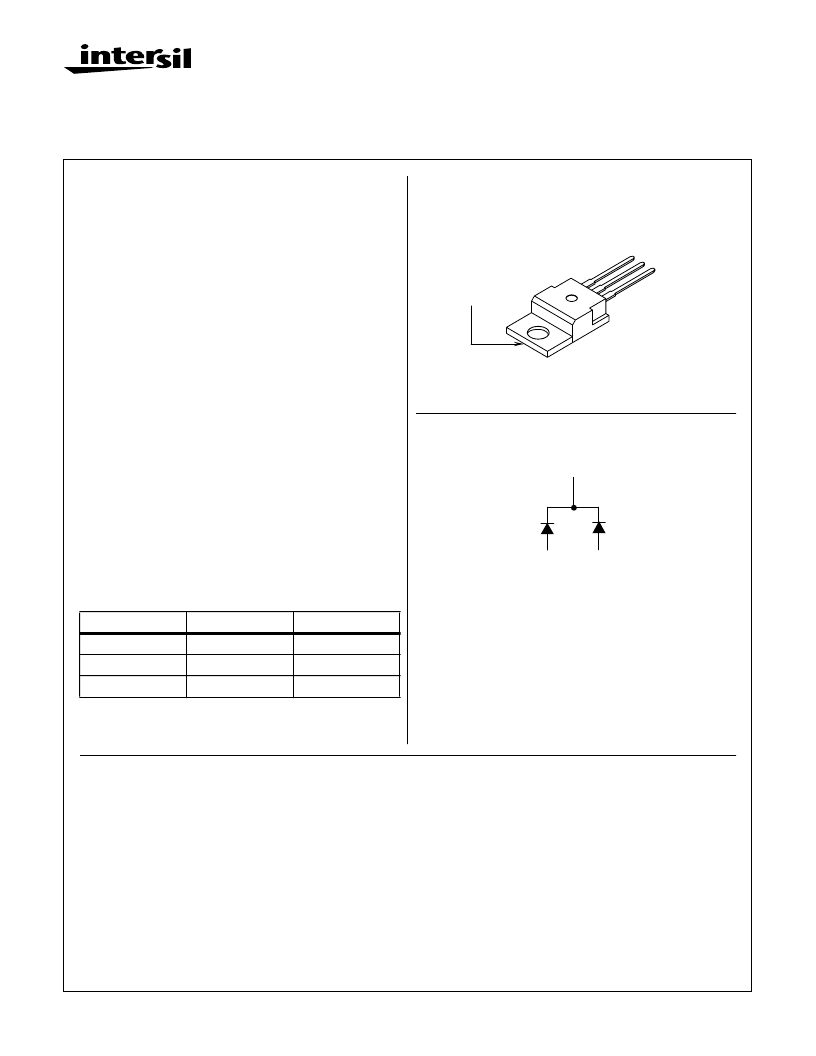
Package
JEDEC TO-220AB
Symbol
CATHODE
ANODE 1
ANODE 2
CATHODE
(FLANGE)
A
1
K
A
2
Features
Ultrafast with Soft Recovery. . . . . . . . . . . . . . . . .<55ns
Operating Temperature . . . . . . . . . . . . . . . . . . . .+175
o
C
Reverse Voltage Up To . . . . . . . . . . . . . . . . . . . . . .600V
Avalanche Energy Rated
Planar Construction
Applications
Switching Power Supplies
Power Switching Circuits
General Purpose
Description
The RURP640CC, RURP650CC, and RURP660CC are
ultrafast dual diodes with soft recovery characteristics (t
RR
<
55ns). They have low forward voltage drop and are silicon
nitride passivated ion-implanted epitaxial planar construc-
tion.
These devices are intended for use as freewheeling/clamp-
ing diodes and rectifiers in a variety of switching power sup-
plies and other power switching applications. Their low
stored charge and ultrafast soft recovery minimize ringing
and electrical noise in many power switching circuits, reduc-
ing power loss in the switching transistors.
NOTE: When ordering, use the entire part number.
Formerly developmental type TA49038.
PACKAGE AVAILABILITY
PART NUMBER
PACKAGE
BRAND
RURP640CC
TO-220AB
RURP640C
RURP650CC
TO-220AB
RURP650C
RURP660CC
TO-220AB
RURP660C
April 1995
Absolute Maximum Ratings
(per leg) T
C
= +25
o
C, Unless Otherwise Specified
RURP640CC
400
400
400
6
RURP650CC
500
500
500
6
RURP660CC
600
600
600
6
UNITS
V
V
V
A
Peak Repetitive Reverse Voltage. . . . . . . . . . . . . . . . . . . . . . . . . . . . V
RRM
Working Peak Reverse Voltage . . . . . . . . . . . . . . . . . . . . . . . . . . . . . V
RWM
DC Blocking Voltage. . . . . . . . . . . . . . . . . . . . . . . . . . . . . . . . . . . . . . . . .V
R
Average Rectified Forward Current . . . . . . . . . . . . . . . . . . . . . . . . . . .I
F(AV)
(T
C
= +155
o
C)
Repetitive Peak Surge Current. . . . . . . . . . . . . . . . . . . . . . . . . . . . . . . I
FSM
(Square Wave, 20kHz)
Nonrepetitive Peak Surge Current . . . . . . . . . . . . . . . . . . . . . . . . . . . . I
FSM
(Halfwave, 1 phase, 60Hz)
Maximum Power Dissipation . . . . . . . . . . . . . . . . . . . . . . . . . . . . . . . . . .P
D
Avalanche Energy (See Figures 10 and 11). . . . . . . . . . . . . . . . . . . . . E
AVL
Operating and Storage Temperature . . . . . . . . . . . . . . . . . . . . . . . T
STG
, T
J
12
12
12
A
60
60
60
A
50
10
50
10
50
10
W
mJ
o
C
-65 to +175
-65 to +175
-65 to +175
File Number
4007
相關(guān)PDF資料 |
PDF描述 |
|---|---|
| RURP8100CC | 8A, 1000V Ultrafast Dual Diode(8A, 1000V 超快速雙二極管) |
| RURP8100 | 8A, 1000V Ultrafast Diodes(8A, 1000V超快二極管,用于開(kāi)關(guān)電源) |
| RURP8100 | 8A, 1000V Ultrafast Diodes |
| RURP8120CC | 8A, 1200V Ultrafast Dual Diode |
| RURP8120 | 8A, 1200V Ultrafast Diode(8A, 1200V超快速二極管) |
相關(guān)代理商/技術(shù)參數(shù) |
參數(shù)描述 |
|---|---|
| RURP810 | 制造商:Rochester Electronics LLC 功能描述:- Bulk |
| RURP8100 | 功能描述:整流器 TO-220AC Ultra Fast RoHS:否 制造商:Vishay Semiconductors 產(chǎn)品:Standard Recovery Rectifiers 配置: 反向電壓:100 V 正向電壓下降: 恢復(fù)時(shí)間:1.2 us 正向連續(xù)電流:2 A 最大浪涌電流:35 A 反向電流 IR:5 uA 安裝風(fēng)格:SMD/SMT 封裝 / 箱體:DO-221AC 封裝:Reel |
| RURP8100 | 制造商:Fairchild Semiconductor Corporation 功能描述:FAST RECOVERY DIODE, 8A, 1KV, TO-220AC |
| RURP8100_NL | 制造商:Fairchild Semiconductor Corporation 功能描述: |
| RURP8100_Q | 功能描述:整流器 TO-220AC Ultra Fast RoHS:否 制造商:Vishay Semiconductors 產(chǎn)品:Standard Recovery Rectifiers 配置: 反向電壓:100 V 正向電壓下降: 恢復(fù)時(shí)間:1.2 us 正向連續(xù)電流:2 A 最大浪涌電流:35 A 反向電流 IR:5 uA 安裝風(fēng)格:SMD/SMT 封裝 / 箱體:DO-221AC 封裝:Reel |
發(fā)布緊急采購(gòu),3分鐘左右您將得到回復(fù)。