- 您現(xiàn)在的位置:買(mǎi)賣(mài)IC網(wǎng) > PDF目錄382380 > PCD4440T (NXP SEMICONDUCTORS) Analog voice scrambler/descrambler PDF資料下載
參數(shù)資料
| 型號(hào): | PCD4440T |
| 廠商: | NXP SEMICONDUCTORS |
| 元件分類(lèi): | 無(wú)繩電話/電話 |
| 英文描述: | Analog voice scrambler/descrambler |
| 中文描述: | TELECOM, CORDLESS, SCRAMBLER/DESCRAMBLER, PDSO8 |
| 封裝: | 7.50 MM, PLASTIC, SOT-176-1, SOP-8 |
| 文件頁(yè)數(shù): | 5/20頁(yè) |
| 文件大小: | 105K |
| 代理商: | PCD4440T |
第1頁(yè)第2頁(yè)第3頁(yè)第4頁(yè)當(dāng)前第5頁(yè)第6頁(yè)第7頁(yè)第8頁(yè)第9頁(yè)第10頁(yè)第11頁(yè)第12頁(yè)第13頁(yè)第14頁(yè)第15頁(yè)第16頁(yè)第17頁(yè)第18頁(yè)第19頁(yè)第20頁(yè)
1996 Dec 20
5
Philips Semiconductors
Product specification
Analog voice scrambler/descrambler
PCD4440T
6
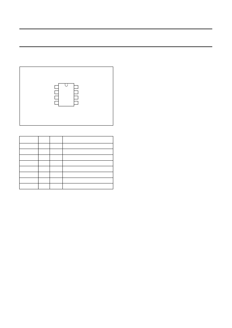
PINNING INFORMATION
6.1
Pinning
6.2
Pin description
7
FUNCTIONAL DESCRIPTION
To provide privacy for the end user of a cordless telephone
set, the radio-link audio signal must be scrambled. In the
microphone of the handset and the incoming telephone
line audio path of the base unit a scrambler circuit has to
be implemented. Consequently the audio signal to the
telephone line and to the earpiece must be descrambled.
Both functions can be fulfilled by the PCD4440T by simply
inserting it in the audio path.
SYMBOL
PIN
TYPE
DESCRIPTION
serial clock line (I
2
C-bus)
serial data line (I
2
C-bus)
negative Supply
signal input
signal output
positive supply
oscillator input
slave address input (I
2
C-bus)
SCL
SDA
V
SS
IN
OUT
V
DD
OSCI
A0
1
2
3
4
5
6
7
8
I
I
P
I
O
P
I
I
handbook, halfpage
1
2
3
4
8
7
6
5
MGG728
PCD4440T
A0
OSCI
SDA
VDD
OUT
IN
VSS
SCL
Fig.2 Pin configuration.
7.1
Scrambling
The PCD4440Taccomplishes this task by first filtering the
incoming signal, limiting the bandwidth to 3500 Hz. Then
the signal is split into a high (
>
f
s
) and a low (
<
f
s
) frequency
band. Both frequency bands are inverted and added again
to provide a single output signal. Values for 9 split
frequencies f
S
can be controlled by a scramble code table
in the microcontroller. Control of these split frequencies is
accomplished via the serial two-wire I
2
C-bus. In addition to
the split frequencies (f
s
), a transparent mode and mute
instruction can be selected (see Table 1).
Figure 3 shows the signal path for both bands. The lower
band path (on the left side of the diagram) operates on
frequencies f
≤
f
s
(Split Frequency), the upper band path
(on the right side) on frequencies f
≥
f
s
.
The input signal contains frequencies from f
1
up to f
2
.
In scrambling mode, the output signal is band limited from
f
l
(300 Hz) to f
h
(3500 Hz). In the left path, the input signal
is first limited to f
s
. The following modulator inverts the
lower band. f
l
is folded up to f
s
, f
s
down to f
l
. In general, an
input frequency f
in
is folded to f
out
= f
s
+ f
l
f
in
. Finally the
folded signal is band limited to f
s
again.
In the right path, the input signal is first limited to f
h
.
The following modulator inverts the upper band. f
s
is folded
up to f
h
, f
h
down to f
s
. In general, an input frequency f
in
is
folded to f
out
= f
s
+ f
h
f
in
. Finally, the folded signal is band
limited to f
h
again. In the last step, the bands are added
and buffered.
Because of the symmetry of the scrambling process,
descrambling is achieved by passing the signal through
another PCD4440T.
In the transparent mode, the input signal is band limited to
3500 Hz. Frequencies from 0 to 300 Hz are not filtered
out.
相關(guān)PDF資料 |
PDF描述 |
|---|---|
| PCD5003A | Enhanced Pager Decoder for POCSAG |
| PCD5003AH | Enhanced Pager Decoder for POCSAG |
| PCD5003 | Advanced POCSAG Paging Decoder |
| PCD5003H | Advanced POCSAG Paging Decoder |
| PCD5008 | FLEX Pager Decoder |
相關(guān)代理商/技術(shù)參數(shù) |
參數(shù)描述 |
|---|---|
| PCD45 | 制造商:IVO 制造商全稱(chēng):Baumer IVO GmbH & Co. KG 功能描述:Process displays electronic |
| PCD45.002PX01 | 制造商:IVO 制造商全稱(chēng):Baumer IVO GmbH & Co. KG 功能描述:Process displays electronic |
| PCD45.003PX01 | 制造商:IVO 制造商全稱(chēng):Baumer IVO GmbH & Co. KG 功能描述:Process displays electronic |
| PCD45.012PX01 | 制造商:IVO 制造商全稱(chēng):Baumer IVO GmbH & Co. KG 功能描述:Process displays electronic |
| PCD45.013PX01 | 制造商:IVO 制造商全稱(chēng):Baumer IVO GmbH & Co. KG 功能描述:Process displays electronic |
發(fā)布緊急采購(gòu),3分鐘左右您將得到回復(fù)。