- 您現(xiàn)在的位置:買賣IC網(wǎng) > PDF目錄369939 > P32P4910A (NXP SEMICONDUCTORS) PRML Read Channel with PR4, 8/9 ENDEC, 4-Burst Servo PDF資料下載
參數(shù)資料
| 型號: | P32P4910A |
| 廠商: | NXP SEMICONDUCTORS |
| 元件分類: | 光電元器件 |
| 英文描述: | PRML Read Channel with PR4, 8/9 ENDEC, 4-Burst Servo |
| 中文描述: | READ CHANNEL, PQFP100 |
| 文件頁數(shù): | 150/196頁 |
| 文件大?。?/td> | 1056K |
| 代理商: | P32P4910A |
第1頁第2頁第3頁第4頁第5頁第6頁第7頁第8頁第9頁第10頁第11頁第12頁第13頁第14頁第15頁第16頁第17頁第18頁第19頁第20頁第21頁第22頁第23頁第24頁第25頁第26頁第27頁第28頁第29頁第30頁第31頁第32頁第33頁第34頁第35頁第36頁第37頁第38頁第39頁第40頁第41頁第42頁第43頁第44頁第45頁第46頁第47頁第48頁第49頁第50頁第51頁第52頁第53頁第54頁第55頁第56頁第57頁第58頁第59頁第60頁第61頁第62頁第63頁第64頁第65頁第66頁第67頁第68頁第69頁第70頁第71頁第72頁第73頁第74頁第75頁第76頁第77頁第78頁第79頁第80頁第81頁第82頁第83頁第84頁第85頁第86頁第87頁第88頁第89頁第90頁第91頁第92頁第93頁第94頁第95頁第96頁第97頁第98頁第99頁第100頁第101頁第102頁第103頁第104頁第105頁第106頁第107頁第108頁第109頁第110頁第111頁第112頁第113頁第114頁第115頁第116頁第117頁第118頁第119頁第120頁第121頁第122頁第123頁第124頁第125頁第126頁第127頁第128頁第129頁第130頁第131頁第132頁第133頁第134頁第135頁第136頁第137頁第138頁第139頁第140頁第141頁第142頁第143頁第144頁第145頁第146頁第147頁第148頁第149頁當前第150頁第151頁第152頁第153頁第154頁第155頁第156頁第157頁第158頁第159頁第160頁第161頁第162頁第163頁第164頁第165頁第166頁第167頁第168頁第169頁第170頁第171頁第172頁第173頁第174頁第175頁第176頁第177頁第178頁第179頁第180頁第181頁第182頁第183頁第184頁第185頁第186頁第187頁第188頁第189頁第190頁第191頁第192頁第193頁第194頁第195頁第196頁

L
G
R
Analog to Digital Converter
General Release Specification
—
Rev. 1.0
148
Analog to Digital Converter
MOTOROLA
12.6.2 A/D Data Register
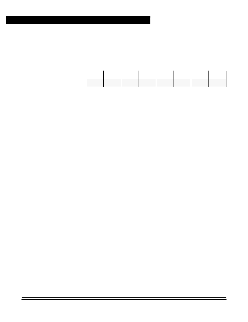
One 8-bit result register is provided. This register is updated each time
COCO is set.
12.7 A/D During WAIT Mode
The A/D converter continues normal operation during WAIT mode. To
decrease power consumption during WAIT, it is recommended that both
the ADON and ADRC bits in the A/D status/control register be cleared if
the A/D converter is not being used. If the A/D converter is in use and
the system clock rate is above 1.0 MHz, it is recommended that the
ADRC bit be cleared.
NOTE:
As the A/D converter continues to function normally in WAIT mode, the
COCO bit is not cleared.
12.8 Analog Input
The external analog voltage value to be converted by the A/D converter
is sampled on an internal capacitor through a resistive path provided by
input-selection switches and a sampling aperture time switch. Sampling
time is limited to 12 bus clock cycles. After sampling, the analog value is
stored on a capacitor and held until the end of conversion. During this
hold time, the analog input is disconnected from the internal A/D system
and the external voltage source sees a high impedance input.
The equivalent analog input during sampling is a RC low-pass filter with
resistance around 50 K
and a capacitance of around 10pF. (It should
be noted that these are typical values measured at room temperature).
$004E
Bit 7
6
5
4
3
2
1
Bit 0
Read:
bit 7
bit 6
bit 5
bit 4
bit 3
bit 2
bit 1
bit 0
Write:
Reset:
U
U
U
U
U
U
U
U
Figure 12-2. A/D Data Register (ADDR)
相關PDF資料 |
PDF描述 |
|---|---|
| P32P4911A | PRML Read Channel with PR4, 8/9 ENDEC, FWR Servo |
| P3500SA | SIDACtor Device |
| P3500S | SIDACtor Device |
| P3500SCMC | solid state crowbar devices |
| P3500SD | solid state crowbar devices |
相關代理商/技術參數(shù) |
參數(shù)描述 |
|---|---|
| P32P4910B | 制造商:未知廠家 制造商全稱:未知廠家 功能描述:Disk Read Data Processor |
| P32P4911A | 制造商:PHILIPS 制造商全稱:NXP Semiconductors 功能描述:PRML Read Channel with PR4, 8/9 ENDEC, FWR Servo |
| P32P4F-F | 制造商:TE Connectivity 功能描述: |
| P32RIGIDT | 制造商:Brady Corporation 功能描述:SIGN NO UNAUTHORISED PERSONS 250X200 |
| P32-S | 制造商:Linemaster Switch Corporation 功能描述:Premier |
發(fā)布緊急采購,3分鐘左右您將得到回復。