- 您現(xiàn)在的位置:買(mǎi)賣IC網(wǎng) > PDF目錄224596 > NCT214MT3R2G (ON SEMICONDUCTOR) SPECIALTY ANALOG CIRCUIT, QCC10 PDF資料下載
參數(shù)資料
| 型號(hào): | NCT214MT3R2G |
| 廠商: | ON SEMICONDUCTOR |
| 元件分類: | 模擬信號(hào)調(diào)理 |
| 英文描述: | SPECIALTY ANALOG CIRCUIT, QCC10 |
| 封裝: | 3 X 3 MM, 0.50 MM PITCH, LEAD FREE, WQFN-10 |
| 文件頁(yè)數(shù): | 14/19頁(yè) |
| 文件大小: | 269K |
| 代理商: | NCT214MT3R2G |
第1頁(yè)第2頁(yè)第3頁(yè)第4頁(yè)第5頁(yè)第6頁(yè)第7頁(yè)第8頁(yè)第9頁(yè)第10頁(yè)第11頁(yè)第12頁(yè)第13頁(yè)當(dāng)前第14頁(yè)第15頁(yè)第16頁(yè)第17頁(yè)第18頁(yè)第19頁(yè)
NCT214
http://onsemi.com
4
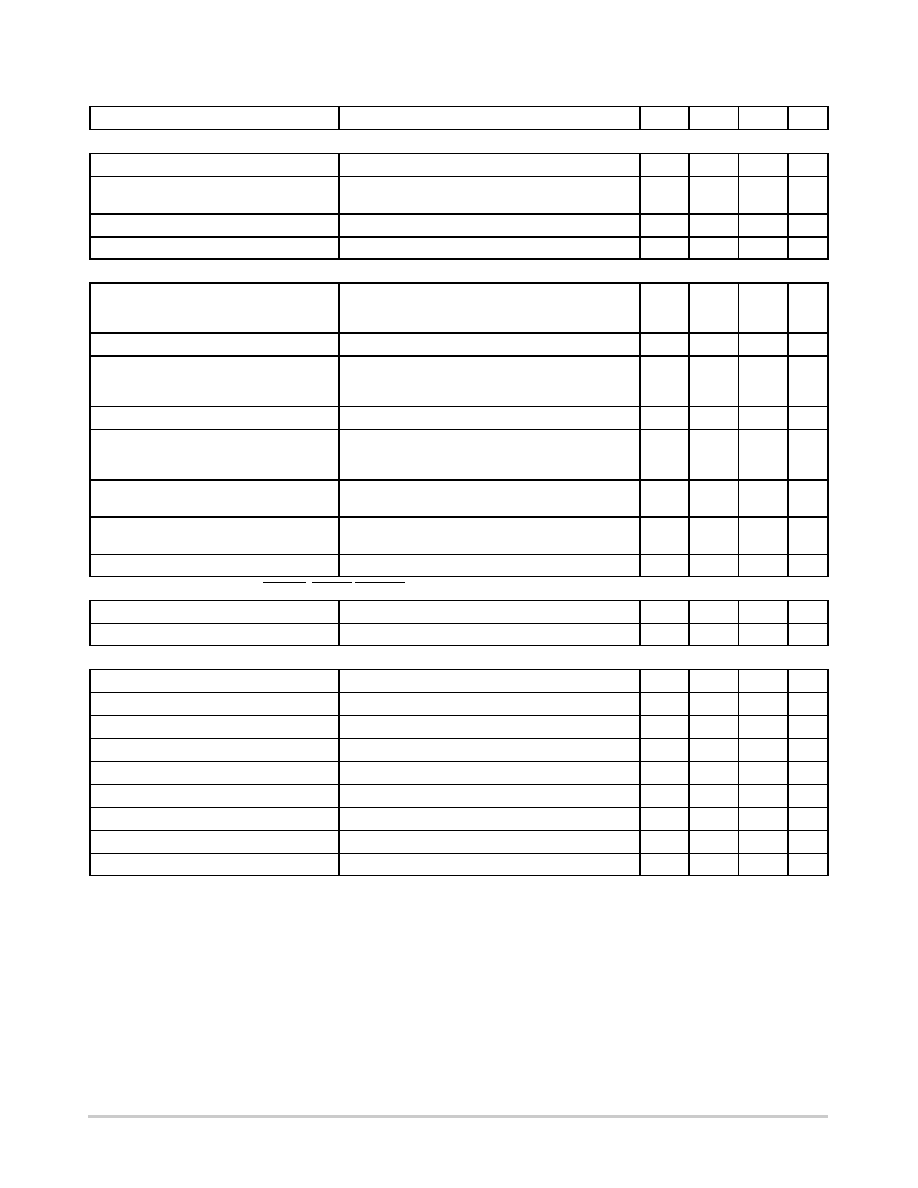
ELECTRICAL CHARACTERISTICS TA = 40°C to +125°C, VDD = 3.0 V to 3.6 V, unless otherwise noted.
Parameter
Conditions
Min
Typ
Max
Unit
Power Supply
Supply Voltage, VDD
3.0
3.30
3.6
V
Average Operating Supply Current, IDD
0.0625 Conversions/Sec Rate (Note 1)
Standby mode
240
5.0
350
30
mA
Undervoltage Lockout Threshold
VDD input, disables ADC, rising edge
2.55
V
PowerOn Reset Threshold
1.0
2.5
V
TemperatureToDigital Converter
Local Sensor Accuracy
0°C ≤ TA ≤ +70°C
0°C ≤ TA ≤ +85°C
40°C ≤ TA ≤ +100°C
±1.0
±1.5
±2.5
°C
Resolution
1.0
°C
Remote Diode Sensor Accuracy
±1.0
±1.5
±2.5
°C
Resolution
0.25
°C
Remote Sensor Source Current
High level (Note 3)
Middle level (Note 3)
Low level (Note 3)
220
82
13.5
mA
Conversion Time
From stop bit to conversion complete, oneshot
mode with averaging switched on
40
52
ms
Oneshot mode with averaging off (that is, conversion
rate = 16, 32, or 64conversions per second)
6.0
8.0
ms
Maximum Series Resistance Cancelled
Resistance split evenly on both the D+ and D– inputs
1.5
kW
OpenDrain Digital Outputs (THERM, ALERT/THERM2)
Output Low Voltage, VOL
IOUT = 6.0 mA
0.4
V
High Level Output Leakage Current, IOH
VOUT = VDD
0.1
1.0
mA
Logic Input High Voltage, VIH SCLK, SDATA
1.4
V
Logic Input Low Voltage, VIL SCLK, SDATA
0.8
V
Hysteresis
500
mV
SDA Output Low Voltage, VOL
0.4
mA
Logic Input Current, IIH, IIL
1.0
+1.0
mA
SMBus Input Capacitance, SCLK, SDATA
5.0
pF
SMBus Clock Frequency
400
kHz
SMBus Timeout (Note 5)
User programmable
25
64
ms
SCLK Falling Edge to SDATA Valid Time
Master clocking in data
1.0
ms
1. See Table 4 for information on other conversion rates.
2. Guaranteed by characterization, but not production tested.
3. Guaranteed by design, but not production tested.
4. See SMBus/I2C Timing Specifications section for more information.
5. Disabled by default. Detailed procedures to enable it are in the Serial Bus Interface section of the datasheet.
相關(guān)PDF資料 |
PDF描述 |
|---|---|
| NDN111-BK | |
| NDN1-WH | |
| NDN3-WH | |
| NDNV4-WH | |
| NDN63-WH | |
相關(guān)代理商/技術(shù)參數(shù) |
參數(shù)描述 |
|---|---|
| NCT218FCT2G | 制造商:ON Semiconductor 功能描述:NCT218 CSP OPN - Tape and Reel 制造商:ON Semiconductor 功能描述:REEL / NCT218 CSP OPN 制造商:ON Semiconductor 功能描述:BATTERY PWR |
| NCT218MTR2G | 制造商:ON Semiconductor 功能描述:LOW VOLTAGE LOCAL TEMPERA - Tape and Reel 制造商:ON Semiconductor 功能描述:REEL / LOW VOLTAGE LOCAL TEMPERA 制造商:ON Semiconductor 功能描述:Low Voltage, High Accuracy Temperature Monitor with I2C Interface |
| NCT22/D | 制造商:未知廠家 制造商全稱:未知廠家 功能描述:Low Cost Single Trip Point Temperature Sensor |
| NCT22DR2 | 制造商:Rochester Electronics LLC 功能描述:- Bulk 制造商:ON Semiconductor 功能描述: |
| NCT24DR2 | 制造商:Rochester Electronics LLC 功能描述:- Bulk |
發(fā)布緊急采購(gòu),3分鐘左右您將得到回復(fù)。