- 您現(xiàn)在的位置:買賣IC網(wǎng) > PDF目錄383645 > MT9079 (Mitel Networks Corporation) Advanced Controller for E1(先進的E1幀調(diào)節(jié)器和控制器) PDF資料下載
參數(shù)資料
| 型號: | MT9079 |
| 廠商: | Mitel Networks Corporation |
| 英文描述: | Advanced Controller for E1(先進的E1幀調(diào)節(jié)器和控制器) |
| 中文描述: | 高級控制器素E1(先進的素E1幀調(diào)節(jié)器和控制器) |
| 文件頁數(shù): | 24/60頁 |
| 文件大?。?/td> | 347K |
| 代理商: | MT9079 |
第1頁第2頁第3頁第4頁第5頁第6頁第7頁第8頁第9頁第10頁第11頁第12頁第13頁第14頁第15頁第16頁第17頁第18頁第19頁第20頁第21頁第22頁第23頁當前第24頁第25頁第26頁第27頁第28頁第29頁第30頁第31頁第32頁第33頁第34頁第35頁第36頁第37頁第38頁第39頁第40頁第41頁第42頁第43頁第44頁第45頁第46頁第47頁第48頁第49頁第50頁第51頁第52頁第53頁第54頁第55頁第56頁第57頁第58頁第59頁第60頁
MT9079
4-230
Transmit Circular Buffers One and Zero (Pages 9
and A)
Page 09H, addresses 10000 to 11111 contain the 16
bytes of transmit circular buffer zero (TxB0.0 to
TxB0.15 respectively). This feature is functional only
in processor and controller modes.
The transmit circular buffers are not cleared by the
RST function, nor are they cleared by the RESET
function.
3
TBUF0
Transmit Buffer Zero Connect. If one,
the contents of the transmit circular
buffer zero will be transmitted in the
corresponding time slot beginning at
the next multiframe boundary. If zero,
circular buffer zero is not connected
to this time slot. This buffer is acces-
sible only in processor and controller
modes.
2
TBUF1
Transmit Buffer One Connect. If one,
the contents of the transmit circular
buffer one will be transmitted in the
corresponding time slot beginning at
the next multiframe boundary. If zero,
circular buffer one is not connected
to this time slot. This buffer is acces-
sible only in processor and controller
modes.
1
RBUF0
Receive Buffer Zero Connect. If one,
the data of the corresponding receive
time slot will be recorded in receive
circular buffer zero beginning at the
next multiframe boundary. If zero, cir-
cular buffer zero is not connected to
this time slot. This buffer is accessi-
ble only in processor and controller
modes.
0
RBUF1
Receive Buffer One Connect. If one,
the data of the corresponding receive
time slot will be recorded in receive
circular buffer one beginning at the
next multiframe boundary. If zero, cir-
cular buffer one will not connected to
this time slot. This buffer is accessi-
ble only in processor and controller
modes.
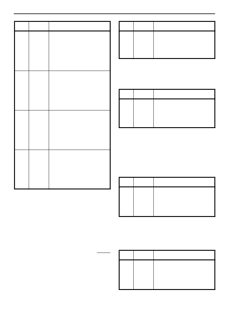
Bit
Name
Functional Description
Table 18 - Per Time Slot Control Words
(Pages 7 and 8) (continued)
.
Page 0AH, addresses 10000 to 11111 contain the 16
bytes of transmit circular buffer one (TxB1.0 to
TxB1.15 respectively). This feature is functional only
in processor and controller modes.
Receive Circular Buffers One and Zero (Pages B
and C)
Page 0BH, addresses 10000 to 11111 contain the 16
bytes of receive circular buffer zero (RxB0.0 to
RxB0.15 respectively). This feature is functional only
in processor and controller modes.
Page 0CH, addresses 10000 to 11111 contain the 16
bytes of receive circular buffer one (RxB1.0 to
RxB1.15 respectively). This feature is functional only
in processor and controller modes.
Bit
Name
Functional Description
7 - 0
TxB0.n .7 -
TxB0.n .0
Transmit Bits 7 to 0. This byte is
transmitted on a time slot selected by
the TBUF0 bit of the appropriate per
time slot control word. n = 0 to 15 and
represents a byte position in Trans-
mit Circular Buffer zero (TxB0).
Table 19 - Transmit Circular Buffer Zero (Page 9)
Bit
Name
Functional Description
7 - 0
TxB1.n .7 -
TxB1.n .0
Transmit Bits 7 to 0. This byte is
transmitted on a time slot selected by
the TBUF1 bit of the appropriate per
time slot control word. n = 0 to 15 and
represents a byte position in Trans-
mit Circular Buffer zero (TxB1).
Table 20 - Transmit Circular Buffer One (Page A)
Bit
Name
Functional Description
7 - 0
RxB0.n .7
-
RxB0.n .0
Receive Bits 7 to 0. This byte is
received from a time slot selected by
the RBUF0 bit of the appropriate per
time slot control words. n = 0 to 15
and represents a byte position in
receive circular buffer zero (RxB0).
Table 21 - Receive Circular Buffer Zero (Page B)
Bit
Name
Functional Description
7 - 0
RxB1.n .7
-
RxB1.n .0
Receive Bits 7 to 0. This byte is
received from a time slot selected by
the RBUF1 bit of the appropriate per
time slot control words. n = 0 to 15
and represents a byte position in
receive circular buffer one (RxB1).
Table 22 - Receive Circular Buffer One (Page C)
相關PDF資料 |
PDF描述 |
|---|---|
| MT9080B | SMX - Switch Matrix Module(用于消費類轉換應用的開關矩陣模塊) |
| MT90810 | Flexible MVIP(Multi-Vendor Integration Protocol) Interface Circuit(彈性MVIP接口電路) |
| MT90812 | Integrated Digital Switch (IDX)(集成數(shù)字開關) |
| MT90840AK | Distributed Hyperchannel Switch |
| MT90840AP | Distributed Hyperchannel Switch |
相關代理商/技術參數(shù) |
參數(shù)描述 |
|---|---|
| MT9079AC | 制造商:MITEL 制造商全稱:Mitel Networks Corporation 功能描述:CMOS ST-BUS? FAMILY Advanced Controller for E1 |
| MT9079AE | 制造商:MITEL 制造商全稱:Mitel Networks Corporation 功能描述:CMOS ST-BUS? FAMILY Advanced Controller for E1 |
| MT9079AL | 制造商:MITEL 制造商全稱:Mitel Networks Corporation 功能描述:CMOS ST-BUS⑩ FAMILY Advanced Controller for E1 |
| MT9079AP | 制造商:MITEL 制造商全稱:Mitel Networks Corporation 功能描述:CMOS ST-BUS⑩ FAMILY Advanced Controller for E1 |
| MT9079APR | 制造商:Microsemi Corporation 功能描述:FRAMER E1 5V 44PLCC - Tape and Reel |
發(fā)布緊急采購,3分鐘左右您將得到回復。