- 您現(xiàn)在的位置:買賣IC網(wǎng) > PDF目錄359234 > MT90401 (Zarlink Semiconductor Inc.) SONET/SDH System Synchronizer PDF資料下載
參數(shù)資料
| 型號(hào): | MT90401 |
| 廠商: | Zarlink Semiconductor Inc. |
| 英文描述: | SONET/SDH System Synchronizer |
| 中文描述: | 的SONET / SDH系統(tǒng)的同步 |
| 文件頁(yè)數(shù): | 26/38頁(yè) |
| 文件大小: | 650K |
| 代理商: | MT90401 |
第1頁(yè)第2頁(yè)第3頁(yè)第4頁(yè)第5頁(yè)第6頁(yè)第7頁(yè)第8頁(yè)第9頁(yè)第10頁(yè)第11頁(yè)第12頁(yè)第13頁(yè)第14頁(yè)第15頁(yè)第16頁(yè)第17頁(yè)第18頁(yè)第19頁(yè)第20頁(yè)第21頁(yè)第22頁(yè)第23頁(yè)第24頁(yè)第25頁(yè)當(dāng)前第26頁(yè)第27頁(yè)第28頁(yè)第29頁(yè)第30頁(yè)第31頁(yè)第32頁(yè)第33頁(yè)第34頁(yè)第35頁(yè)第36頁(yè)第37頁(yè)第38頁(yè)
MT90401
Data Sheet
26
Zarlink Semiconductor Inc.
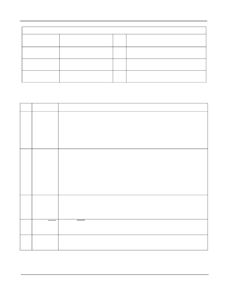
0EH
Reserved
Read
Only
0FH (Table 11)
Identification Word
Read
Only
ID7-0
10H
Reserved
Read/
Write
Set all bits to zero.
Bit
Name
Functional Description
7
RSEL
Reference Select
. A zero selects the PRI (primary) reference source as the input
reference signal and a one selects the SEC (secondary) reference. Switching between
reference clocks operating at 8 kHz, 1.544 MHz and 2.048 MHz can be done at any time
and without any special setup procedures. However it is recommended that the switching
of the 19.44 MHz references will be performed by forcing PLL temporary into Holdover
mode (MS2,MS1=01) to prevent excessive phase accumulation in the internal controller.
The PLL can be switched back to Normal mode (MS2,MS1= 00) 250 us after the new
input reference has been selected.
6 - 5
FS2-1
Frequency Select 2 - 1
. These bits select which of four possible frequencies (8 kHz,
1.544 MHz, 2.048 MHz or 19.44 MHz) may be input to the PRI and SEC inputs.
FS2 - 0, FS1 - 0 = 19.44 MHz
FS2 - 0, FS1 - 1 = 8 kHz.
FS2 - 1, FS1 - 0 = 1.544 MHz.
FS2 - 1, FS1 - 1 = 2.048 MHz.
When “19.44 MHz” reference clock option is selected, a loss of 19.44 MHz clock or a
larger than 30000 ppm frequency deviation may create a frequency step exceeding ±4.6
ppm upon return from Auto-Holdover mode. This may result in a lock time that is longer
than normally guaranteed.
4 - 3
MS2-1
Mode Select 2 - 1
: These bits select the PLL state of operation.
MS2 - 0, MS1 - 0 = Normal.
MS2 - 0, MS1 - 1 = Holdover.
MS2 - 1, MS1 - 0 = Freerun.
MS2 - 1, MS1 - 1 = Reserved.
2
SONET/SDH
SONET / SDH
. Set to one to move the loop filter corner frequency to 70 millihertz and
limit the phase slope to 885 ns per second as per SONET requirements. Set to zero to
move the corner frequency to 1.1 Hz and limit the phase slope to 53 ns per 1.326 ms.
1
FLOCK
Fast Lock
. Set to one to allow the PLL to lock faster than normal to the input reference.
During the time that FLOCK is one, the wander generation of the PLL is, of necessity,
compromised. Set to zero for normal operation.
Table 6 - Control Register 1 (Address 00H - Read/Write)
Control and Status Registers (continued)
Address
(A
6
A
5
A
4
A
3
A
2
A
1
A
0
)
Register
Read/
Write
Function
Table 5 - Register Map (continued)
相關(guān)PDF資料 |
PDF描述 |
|---|---|
| MT90401AB | 150MA LOW-DROPOUT VOLTAGE REGULATOR SO-8 PKG |
| MT90401AB1 | SONET/SDH System Synchronizer |
| MT9040 | T1/E1 Synchronizer |
| MT9040AN | T1/E1 Synchronizer |
| MT9043 | T1/E1 System Synchronizer |
相關(guān)代理商/技術(shù)參數(shù) |
參數(shù)描述 |
|---|---|
| MT90401AB | 制造商:ZARLINK 制造商全稱:Zarlink Semiconductor Inc 功能描述:SONET/SDH System Synchronizer |
| MT90401AB1 | 制造商:Microsemi Corporation 功能描述:FRAMER SDH/SONET 3.3V 80LQFP EP - Trays 制造商:MICROSEMI CONSUMER MEDICAL PRODUCT GROUP 功能描述:IC SYNCHRONIZER SONET/SDH 80LQFP 制造商:Microsemi Corporation 功能描述:IC SYNCHRONIZER SONET/SDH 80LQFP |
| MT9040AN | 制造商:ZARLINK 制造商全稱:Zarlink Semiconductor Inc 功能描述:T1/E1 Synchronizer |
| MT9040AN1 | 制造商:Microsemi Corporation 功能描述:FRAMER E1 /T1 3.3V 48SSOP - Rail/Tube |
| MT9040ANR1 | 制造商:Microsemi Corporation 功能描述:FRAMER E1 /T1 3.3V 48SSOP - Tape and Reel |
發(fā)布緊急采購(gòu),3分鐘左右您將得到回復(fù)。