- 您現(xiàn)在的位置:買賣IC網(wǎng) > PDF目錄383643 > MT8977AP (Mitel Networks Corporation) Ultraframer DS3/E3/DS2/E2/DS1/E1/DS0 PDF資料下載
參數(shù)資料
| 型號: | MT8977AP |
| 廠商: | Mitel Networks Corporation |
| 元件分類: | 通信及網(wǎng)絡(luò) |
| 英文描述: | Ultraframer DS3/E3/DS2/E2/DS1/E1/DS0 |
| 中文描述: | Ultraframer DS3/E3/DS2/E2/DS1/E1/DS0 |
| 文件頁數(shù): | 14/26頁 |
| 文件大小: | 344K |
| 代理商: | MT8977AP |
第1頁第2頁第3頁第4頁第5頁第6頁第7頁第8頁第9頁第10頁第11頁第12頁第13頁當(dāng)前第14頁第15頁第16頁第17頁第18頁第19頁第20頁第21頁第22頁第23頁第24頁第25頁第26頁
MT8977
ISO-CMOS
Preliminary Information
4-112
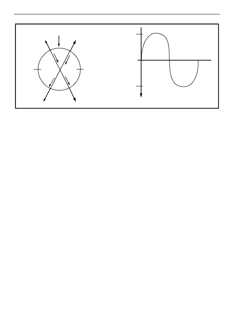
Figure 8 - Elastic Buffer Functional Diagram (156 UI Wander Tolerance)
Write
Pointer
60 CH
2 CH
47 CH
15 CH
34 CH
28 CH
386 Bit
Elastic
Store
13 CH
-13 CH
Wander Tolerance
decrease over time. When this delay approaches
the minimum two channel threshold, the buffer will
perform a controlled slip, which will reset the internal
ST-BUS read pointers so that there is exactly 34
channels delay between the two pointers. This will
result in
some
ST-BUS channels
information output in the previous frame. Repetition
of up to one DS1 frame of information is possible.
containing
Conversely, if the data on the DS1 side is being
written into the buffer at a rate faster than it is being
read out on the ST-BUS side, the delay between the
DS1 frame and the ST-BUS frame will increase over
time. A controlled slip will be performed when the
throughput delay exceeds 60 ST-BUS channels.
This slip will reset the internal ST-BUS counters so
that there is a 28 channel delay between the DS1
write pointer and the ST-BUS read pointer, resulting
in loss of up to one frame of received DS1 data.
Figure 8 illustrates the relationship between the read
and write pointers of the receive elastic buffer.
Measuring clockwise from the write pointer, if the
read pointer comes within two channels of the writer
pointer a frame slip will occur, which will put the read
pointer 34 channels from the write pointer.
Conversely, if the read pointer moves more than 60
channels from the write pointer, a slip will occur,
which will put the read pointer 28 channels from the
write pointer. This provides a worst case hysteresis
of 13 ST-BUS channels peak (26 ST-BUS channels
peak-to-peak). This can be translated into a low
frequency jitter (wander) tolerance value, accounting
for the DS1 to ST-BUS rate conversion, as follows:
(1.544/2.048) X 26 X 8 = 156 UI pp.
There is no loss of frame sync, multiframe sync or
any errors in the signalling bits when the device
performs a slip. The information on the FDL pins in
ESF or SLC-96 mode will, however, undergo slips at
the same time.
Framing Algorithm
In ESF mode, the framer searches for a correct FPS
pattern. Figure 9 shows a state diagram of the
framing algorithm. The dotted lines show which
feature can be switched in and out depending upon
the operating mode of the device.
When the device is operating in the D3/D4 format,
the framer searches for the F
T
pattern, i.e., a
repeating 1010... pattern in a specific bit position
every alternate frame. It will synchronize to this
pattern
and
declare
synchronization by clearing bit 0 in Master Status
Word 1. The device will subsequently initiate a
search for the F
S
pattern to locate the signalling
frames (see Table 4). When a correct F
S
pattern has
been located, bit 3 in Master Status Word 1 is
cleared indicating that the device has achieved
multiframe synchronization.
valid
terminal
frame
Note: the device will remain in terminal frame
synchronization even if no F
S
pattern can be located.
In D3/D4 format, when the CRC/MIMIC bit in Master
Control Word 1 is cleared, the device will not go into
synchronization if more than one bit position in the
frame has a repeating 1010.... pattern, i.e., if more
than one candidate for the terminal framing position
is located. The framer will continue to search until
only one terminal framing pattern candidate is
相關(guān)PDF資料 |
PDF描述 |
|---|---|
| MT8979 | Ultraframer DS3/E3/DS2/E2/DS1/E1/DS0 |
| MT8979 | Ultraframer DS3/E3/DS2/E2/DS1/E1/DS0 |
| MT8979AE | Ultraframer DS3/E3/DS2/E2/DS1/E1/DS0 |
| MT8979AP | Ultraframer DS3/E3/DS2/E2/DS1/E1/DS0 |
| MT8979AC | Ultraframer DS3/E3/DS2/E2/DS1/E1/DS0 |
相關(guān)代理商/技術(shù)參數(shù) |
參數(shù)描述 |
|---|---|
| MT8977APR | 制造商:Rochester Electronics LLC 功能描述: 制造商:Zarlink Semiconductor Inc 功能描述: 制造商:ZARLINK 功能描述: |
| MT8979 | 制造商:MITEL 制造商全稱:Mitel Networks Corporation 功能描述:ISO-CMOS ST-BUS⑩ FAMILY CEPT PCM 30/CRC-4 Framer & Interface |
| MT8979AC | 制造商:MITEL 制造商全稱:Mitel Networks Corporation 功能描述:ISO-CMOS ST-BUS⑩ FAMILY CEPT PCM 30/CRC-4 Framer & Interface |
| MT8979AE | 制造商:Microsemi Corporation 功能描述: 制造商:Zarlink Semiconductor Inc 功能描述: |
| MT8979AE1 | 制造商:Microsemi Corporation 功能描述:FRAMER CRC-4/PCM 30 5V 28PDIP - Rail/Tube 制造商:Zarlink Semiconductor Inc 功能描述:FRAMER CRC-4/PCM 30 5V 28PDIP - Rail/Tube |
發(fā)布緊急采購,3分鐘左右您將得到回復(fù)。