- 您現(xiàn)在的位置:買賣IC網(wǎng) > PDF目錄383643 > MT8950AC (Mitel Networks Corporation) ISO-CMOS ST-BUS⑩ FAMILY Data Codec PDF資料下載
參數(shù)資料
| 型號(hào): | MT8950AC |
| 廠商: | Mitel Networks Corporation |
| 元件分類: | Codec |
| 英文描述: | ISO-CMOS ST-BUS⑩ FAMILY Data Codec |
| 中文描述: | 異意法半導(dǎo)體的CMOS總線⑩系列數(shù)據(jù)編解碼器 |
| 文件頁數(shù): | 11/16頁 |
| 文件大小: | 223K |
| 代理商: | MT8950AC |
ISO-CMOS
MT8950
6-13
Codec converts analog signals into the ST-BUS
format while the Data Codec does a similar
conversion for low speed data. The information in
the ST-BUS format can be switched via the Digital
Switch to any of the other interfaces and
subsequently transmitted over the appropriate lines
to the remote destination. At the remote end, the
original signal is regenerated by another codec.
The remote equipment can be part of a local area
network or it may be accessed through leased T1/
CEPT digital lines. Access to remote equipment via
the T1/CEPT leased lines is acquired through the T1/
CEPT interface (MT8976). Full duplex transmission
at 1.544 or 2.048 Mbps is possible with this interface.
The Digital Network Interface Circuit (DNIC), the
MT8972, is capable of providing 160 kbps full duplex
transmission over single telephone pair wiring. This
device can support two 64 kbps channels, allowing
two data codecs to be interfaced to it at the remote
end. Simple, low cost data sets can be constructed
using the data codec and the DNIC.
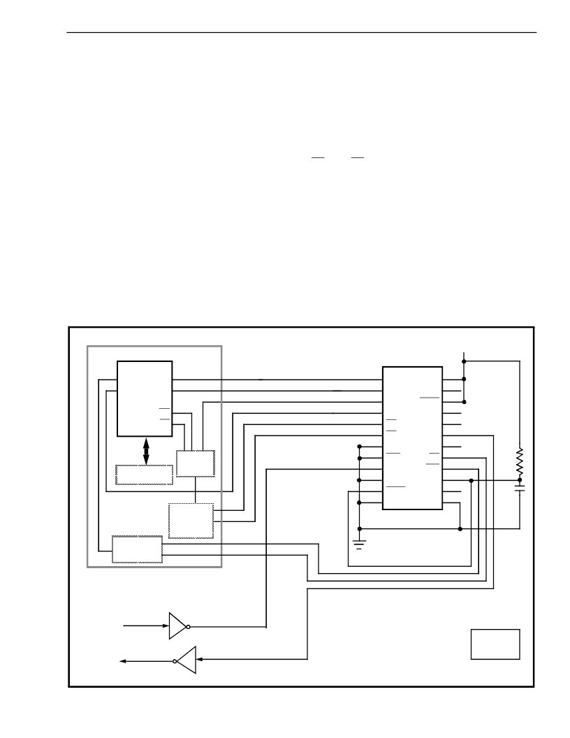
A simplified interface for transmitting and receiving
RS-232 data signals is illustrated in Figure 9. The
Codec is selected to receive and transmit low speed
data in the NRZ format. The data transmitted by the
terminal equipment in the RS-232 format is inverted
and level shifted to TTL-compatible levels before
being fed into the D
X
1 input on the Codec. The
signal is converted into the ST-BUS format and
transmitted via the DSTo output in one channel
timeslot when the ST-BUS interface is enabled by
F1i and CA, as dictated by the system channel
assignment scheme. During this same time period
the Codec accepts the 8 bit data arriving on the
incoming ST-BUS stream which is output at the STo1
pin on the MT8980. The data is decoded and the
original signal input at the remote end is regenerated
and output at the D
R
1 pin. This signal is level
shifted, inverted and transmitted to the terminal. The
codec in this particular application requires no other
programming. Loading of the Control Register via
the CSTi input is optional. If this input is tied to
ground, the Codec will operate in mode 0 (the normal
mode). Note that the SCLK input is tied low. Thus
synchronization pulses will not be transmitted and
Figure 9 - Simplified RS-232 Interface using the Data Codec
AAAA
AA
AAAA
AAAA
Scan Point
Interface
AAAA
AAAA
AAAA
AAAA
AAAA
AA
AA
AA
AA
AA
AA
AA
AAAA
AAAA
AAAA
AAAA
AAAA
AAAA
AAA
AAA
AA
AA
AA
AA
AAAA
AA
AAAA
AAAA
Timing
Circuitry
AAAA
AAAA
AAAA
A
A
A
A
A
A
AAAAAAAAAAAA
AA
AA
AA
AA
AA
AAAA
AA
AAAA
AAAA
AAAA
AAAA
MPU
AAAA
AAAA
AAAA
A
A
A
A
A
A
AAAAAAAAAAAAAAAAA
AA
AA
AA
R = 210 K
C = 1.0
μ
F
Channel
Assignment
Circuit
AAAAAAAAAAAAAA
AA
AA
AA
AA
AA
AA
AA
AA
AA
AA
AA
AAAAAAAAAAAAA
AA
AA
AA
AA
AA
AA
AA
AA
Digital Switch
MT8980
STi3
STi1
STo0
STo1
C4i
F0i
Line Drivers
/Receivers
TxD
RxD
RS-232
TTL
FROM
DTE
1
2
3
4
5
6
7
8
9
10
11
12
13
14
15
16
17
18
19
20
21
22
23
24
CSTi
DSTi
C2i
DSTo
F1i
CA
DF
RxE
D
X
1
D
X
2
NRZo
V
SS
V
DD
NC
PRST
NC
NC
D
R
1
D
R
2
DA
SPo
SPi
DP
SCLK
+ 5V
R
C
MT8950
相關(guān)PDF資料 |
PDF描述 |
|---|---|
| MT8952BC | ISO-CMOS ST-BUS⑩ FAMILY HDLC Protocol Controller |
| MT8952BE | ISO-CMOS ST-BUS⑩ FAMILY HDLC Protocol Controller |
| MT8952BP | ISO-CMOS ST-BUS⑩ FAMILY HDLC Protocol Controller |
| MT8952BS | ISO-CMOS ST-BUS⑩ FAMILY HDLC Protocol Controller |
| MT8952 | ISO-CMOS ST-BUS⑩ FAMILY HDLC Protocol Controller |
相關(guān)代理商/技術(shù)參數(shù) |
參數(shù)描述 |
|---|---|
| MT8952 | 制造商:MITEL 制造商全稱:Mitel Networks Corporation 功能描述:ISO-CMOS ST-BUS⑩ FAMILY HDLC Protocol Controller |
| MT8952B | 制造商:MITEL 制造商全稱:Mitel Networks Corporation 功能描述:ISO-CMOS ST-BUS⑩ FAMILY HDLC Protocol Controller |
| MT8952B-1 | 制造商:MITEL 制造商全稱:Mitel Networks Corporation 功能描述:ISO-CMOS ST-BUS⑩ FAMILY HDLC Protocol Controller |
| MT8952BC | 制造商:MITEL 制造商全稱:Mitel Networks Corporation 功能描述:ISO-CMOS ST-BUS⑩ FAMILY HDLC Protocol Controller |
| MT8952BE | 制造商:MITEL 制造商全稱:Mitel Networks Corporation 功能描述:ISO-CMOS ST-BUS⑩ FAMILY HDLC Protocol Controller |
發(fā)布緊急采購,3分鐘左右您將得到回復(fù)。