- 您現(xiàn)在的位置:買賣IC網(wǎng) > PDF目錄383642 > MT8931B (Mitel Networks Corporation) () PDF資料下載
參數(shù)資料
| 型號(hào): | MT8931B |
| 廠商: | Mitel Networks Corporation |
| 英文描述: | () |
| 中文描述: | () |
| 文件頁(yè)數(shù): | 9/29頁(yè) |
| 文件大?。?/td> | 277K |
| 代理商: | MT8931B |
第1頁(yè)第2頁(yè)第3頁(yè)第4頁(yè)第5頁(yè)第6頁(yè)第7頁(yè)第8頁(yè)當(dāng)前第9頁(yè)第10頁(yè)第11頁(yè)第12頁(yè)第13頁(yè)第14頁(yè)第15頁(yè)第16頁(yè)第17頁(yè)第18頁(yè)第19頁(yè)第20頁(yè)第21頁(yè)第22頁(yè)第23頁(yè)第24頁(yè)第25頁(yè)第26頁(yè)第27頁(yè)第28頁(yè)第29頁(yè)
Application Note
MSAN-141
A-209
All the time intervals mentioned above are inherent
in the SNIC silicon. The response time to the INFO
signals are relevant to the detection algorithms for
each signals. (These algorithms are detailed in the
following section.) The timer (timer 2) implemented
on the SNIC, (to avoid unintentional reactivation of
the NT) has been set to 32 ms which is well in the
range of 25 to 100 ms specified above.
2.3.3
INFO Detection Algorithms
The activation times for the TE and the NT, are
determined by the detection algorithms for the
INFO0 through INFO4 signals. The detection
scheme used for the INFO signals will identify the
worst case detection time under no-fault conditions.
The MT8930B/31B uses a combination of an energy
detection circuit in conjunction with a timer in order
to detect the INFO1 signal. The detection of INFO2
relies on the convergence of the PLL as well as the
framer of the MT8930B/31B. Once activity occurs on
the line, the PLL will train the clocks to the correct
frequency before sampling the received data. The
INFO2 signal is detected upon the occurrence of a
synchronized state with the AR bit set to binary”0”.
Therefore, under normal conditions (no errors), the
worst case synchronization time is two frames
following the convergence of the PLL.
The NT detects the reception of INFO3 upon the
synchronization of the incoming signal. Since the
PLL need not be trained, the detection of INFO3 is
directly related to the synchronization algorithm.
The INFO4 signal is identified by the status of the A-
bit. If the TE is synchronized to the received line
signal, it will identify INFO4 on the first occurrence of
the A-bit = 1
B
. Therefore, the detection and reporting
of the A-bit will occur within two ST-BUS frames or
250
μ
s.
The SNIC provides an internal signal labelled “Bus
Activity“. This signal will go high when three zeros
are received in a time period equivalent to 48 bits or
250
μ
s. Receiving 128 consecutive ONEs resets this
signal. This scheme allows the detection of INFO0 in
about 667
μ
s. Bit 7 of the Mode Status Register
reflects the binary value of this signal.
2.4
D-Channel Access
In a multidrop configuration, a systematic approach
is required to allow competing TEs access to the
single 16 kbit/s D-channel. A layer 1 priority scheme
has been implemented to allocate terminal priority as
well as provide contention resolution.
A TE gains access to the D-channel when it reaches
its priority count. This is accomplished by monitoring
the received D-echo channel (E-bit) transmitted from
the NT and counting the number of consecutive
binary ones. Any zero received on the E-bit will
restart the counting process. The priority mechanism
is based on this counting process, such that, a TE
can only start transmitting once the counter is equal
to, or exceeds the value of its priority class.
Any TE which is not using the on-chip HDLC, (using
ST-BUS D-Channel) must request access to the D-
channel by raising the DReq bit (B3 of the TE mode
C-channel Control Register). The user must wait
until the D-channel acknowledgment bit (Dack) (B0
of the TE mode C-channel Status Register) is
received before forwarding the packet. If the TE fails
to respond to the Dack within an eight bit interval,
access to the D-channel may be lost as the priority
count on another TE may be attained.
The priority mechanism circuitry is activated once
the HDLC transmitter is enabled and data is written
to the TxFIFO.
2.4.1
Priority Classes
Using the counting algorithm mentioned above, the
MT8930B/31B can establish four levels of priority.
These priority levels are split into two classes, which
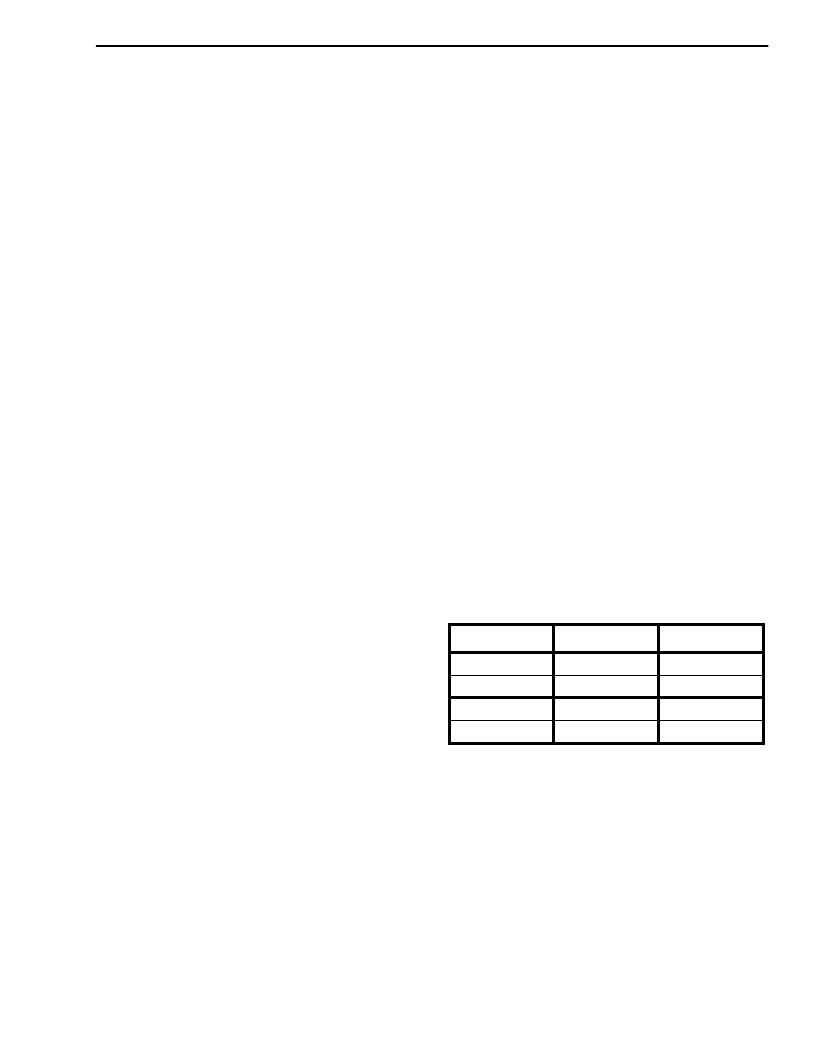
are subdivided into two levels (refer to Table 4). Only
the class of priority is accessible to the user through
B4 of the TE mode C-channel control register.
Table 4. Priority Classes
The level of priority is strictly internal to the device
and cannot be accessed by the user. In a priority
class, the level of priority is changed from high to low
when the TE has successfully completed its
transmission. The level of priority is reinstated only
after the priority count for the respective TE has
been attained.
2.4.2
Collision Detection
The D-echo channel is also used to detect
contention on the D-channel. The TEs which are
trying to access the D-channel will monitor the E-bit
Class
Level
Count
High
High
8
High
Low
9
Low
High
10
Low
Low
11
相關(guān)PDF資料 |
PDF描述 |
|---|---|
| MT8930C-1 | SWITCH, ON-OFF, CHROM/BLK BTN; Switch function type:SPST Latching; Voltage, contact AC max:125V; Voltage, contact DC max:24V; Temp, op. max:85(degree C); Temp, op. min:-40(degree C); Diameter, panel cut-out:13.6mm; Length / Height, RoHS Compliant: Yes |
| MT8930C | Subscriber Network Interface Circuit(用戶網(wǎng)絡(luò)接口電路(提供點(diǎn)到點(diǎn)或點(diǎn)到多點(diǎn)數(shù)字傳送)) |
| MT8930 | CMOS ST-BUS⑩ FAMILY Subscriber Network Interface Circuit Preliminary Information |
| MT8930C | CMOS ST-BUS⑩ FAMILY Subscriber Network Interface Circuit Preliminary Information |
| MT8930CC | CMOS ST-BUS⑩ FAMILY Subscriber Network Interface Circuit Preliminary Information |
相關(guān)代理商/技術(shù)參數(shù) |
參數(shù)描述 |
|---|---|
| MT8931BC | 制造商:MITEL 制造商全稱:Mitel Networks Corporation 功能描述:Subscriber Network Interface Circuit |
| MT8931BE | 制造商:MITEL 制造商全稱:Mitel Networks Corporation 功能描述:Subscriber Network Interface Circuit |
| MT8931BP | 制造商:MITEL 制造商全稱:Mitel Networks Corporation 功能描述:Subscriber Network Interface Circuit |
| MT8931C | 制造商:ZARLINK 制造商全稱:Zarlink Semiconductor Inc 功能描述:Subscriber Network Interface Circuit |
| MT8931C-1 | 制造商:MITEL 制造商全稱:Mitel Networks Corporation 功能描述:CMOS ST-BUS⑩ FAMILY Subscriber Network Interface Circuit |
發(fā)布緊急采購(gòu),3分鐘左右您將得到回復(fù)。