- 您現(xiàn)在的位置:買賣IC網(wǎng) > PDF目錄383602 > MH89760BN (Mitel Networks Corporation) Ultraframer DS3/E3/DS2/E2/DS1/E1/DS0 PDF資料下載
參數(shù)資料
| 型號(hào): | MH89760BN |
| 廠商: | Mitel Networks Corporation |
| 元件分類: | 通信及網(wǎng)絡(luò) |
| 英文描述: | Ultraframer DS3/E3/DS2/E2/DS1/E1/DS0 |
| 中文描述: | Ultraframer DS3/E3/DS2/E2/DS1/E1/DS0 |
| 文件頁(yè)數(shù): | 24/38頁(yè) |
| 文件大小: | 846K |
| 代理商: | MH89760BN |
第1頁(yè)第2頁(yè)第3頁(yè)第4頁(yè)第5頁(yè)第6頁(yè)第7頁(yè)第8頁(yè)第9頁(yè)第10頁(yè)第11頁(yè)第12頁(yè)第13頁(yè)第14頁(yè)第15頁(yè)第16頁(yè)第17頁(yè)第18頁(yè)第19頁(yè)第20頁(yè)第21頁(yè)第22頁(yè)第23頁(yè)當(dāng)前第24頁(yè)第25頁(yè)第26頁(yè)第27頁(yè)第28頁(yè)第29頁(yè)第30頁(yè)第31頁(yè)第32頁(yè)第33頁(yè)第34頁(yè)第35頁(yè)第36頁(yè)第37頁(yè)第38頁(yè)
4-78
MH89760B
Preliminary Information
The channel assignment circuit is therefore very
simple.
The switch matrix, in the message mode, passes
monitor and control information between the
microprocessor and the T1 interface over ST-BUS
stream 0. The MT8980 is also used to reformat the
ST-BUS data streams between
converter and the MH89760B interface.
the protocol
The MH89760B and the MT8941 form the T1
interface. The MH89760B converts the data received
on the ST-BUS into a 1.544 MHz T1 stream. All of
the formatting and decoding of the T1 signal is
performed by this device. The MT8941 provides the
clock synchronization required to operate in a loop
timed mode. Digital phase-locked loop #2 provides
ST-BUS clocks that are synchronized to the
extracted 8kHz, and digital phase-locked loop #1
provides the transmit 1.544 MHz clock synchronized
to the ST-BUS.
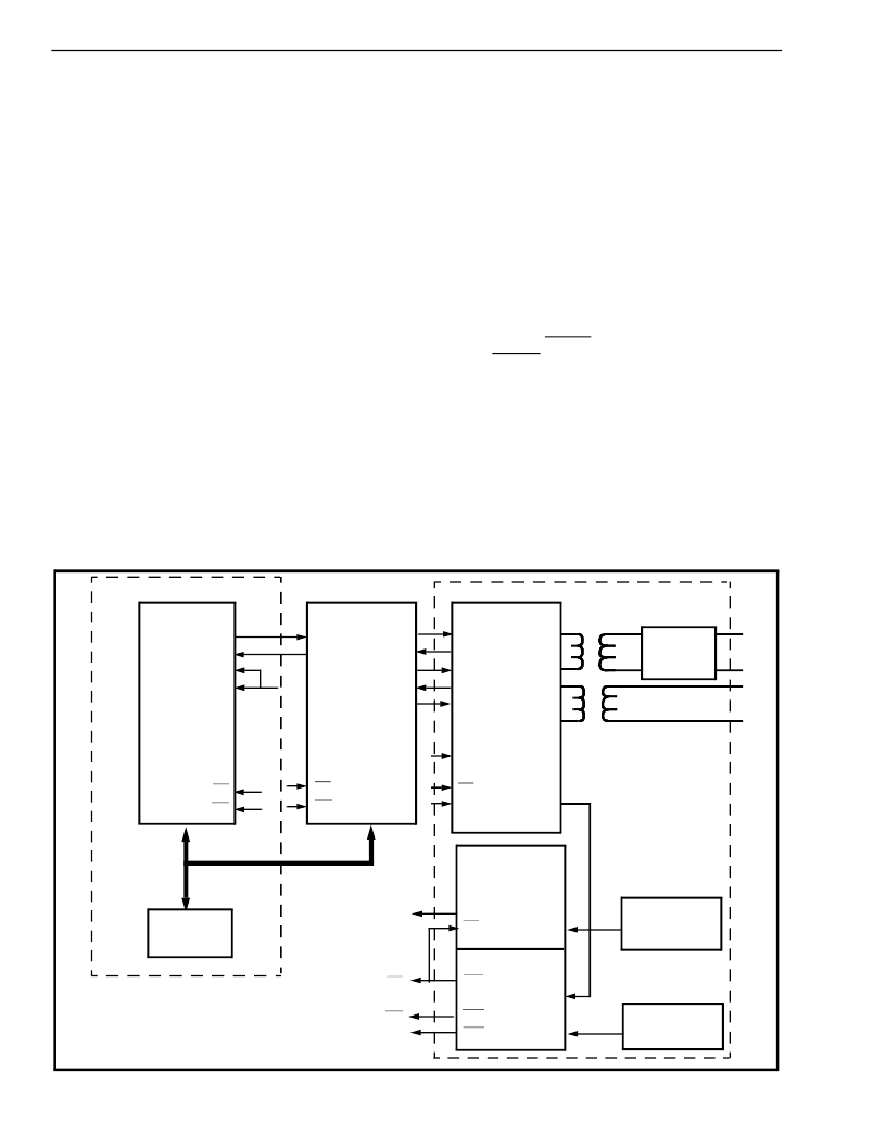
7. High Speed Data Transmission Link
High speed data links are becoming increasingly
popular
in
private
networks
and
computer
communications. The basic mode of transmission is
to assemble data into packets (e.g., HDLC or
ethernet) which are transported on a T1 link
configured as a 1.536 Mbit/s serial channel. No T1
repeaters are required if the transmission link length
is 1300 ft. or less (e.g., business complex or
university). However, if the transmission link length is
greater than 1300 ft., a repeatered T1 line must be
leased from the local telephone operating company.
which are the protocol converter, switch matrix, and
T1 interface. The protocol section is dependent on
the particular format that is chosen. In this example it
is assumed that the protocol is HDLC. The Transmit
Clock Enable (TxCEN) and the Receive Clock
Enable (RxCEN) of the MT8952 are active for a
period of 24 consecutive ST-BUS channels, and the
clock speed is 2.048 MHz. This enables the protocol
conversion section to interface directly to the switch
matrix. The switch matrix switches the first 24
channels received from the protocol section into the
24 valid timeslots used by the MH89760B. Once the
data enters the T1 interface the MH89760B formats
and transmits the data on the T1 line.
Figure 17 - High Speed Data Transmission Link
Protocol Converter
MT8952
CDSTo
CDSTi
TxCEN
RxCEN
F0i
C4i
MICRO
MT8980
STi0
STo0
STo1
STi1
STo2
STi2
STo3
F0i
C4i
MH89760B
DSTi
DSTo
CSTi1
CSTo
CSTi0
C2i
C1.5i
OUTA
OUTB
RxT
RxR
E8Ko
F0i
MT8941
DPLL #1
CVb
F0i
C1.5i
C12i
DPLL #2
F0b
C4b
C20
C8Kb
C16i
C4i
C2i
F0i
EQUAL
-
IZER
12.352
MHz Osc.
16.384
MHz Osc.
T1 Interface
Switch Matrix
相關(guān)PDF資料 |
PDF描述 |
|---|---|
| MH89760BS | Ultraframer DS3/E3/DS2/E2/DS1/E1/DS0 |
| MH89761 | T1 Transmit Equalizer Advance Information |
| MH89770N | Ultraframer DS3/E3/DS2/E2/DS1/E1/DS0 |
| MH89770 | Ultraframer DS3/E3/DS2/E2/DS1/E1/DS0 |
| MH89770S | Ultraframer DS3/E3/DS2/E2/DS1/E1/DS0 |
相關(guān)代理商/技術(shù)參數(shù) |
參數(shù)描述 |
|---|---|
| MH89760BS | 制造商:MITEL 制造商全稱:Mitel Networks Corporation 功能描述:ST-BUS⑩ FAMILY T1/ESF Framer & Interface Preliminary Information |
| MH89761 | 制造商:MITEL 制造商全稱:Mitel Networks Corporation 功能描述:T1 Transmit Equalizer Advance Information |
| MH89770 | 制造商:MITEL 制造商全稱:Mitel Networks Corporation 功能描述:T1/ESF Framer & Interface Preliminary Information |
| MH89770N | 制造商:MITEL 制造商全稱:Mitel Networks Corporation 功能描述:T1/ESF Framer & Interface Preliminary Information |
| MH89770S | 制造商:MITEL 制造商全稱:Mitel Networks Corporation 功能描述:T1/ESF Framer & Interface Preliminary Information |
發(fā)布緊急采購(gòu),3分鐘左右您將得到回復(fù)。