- 您現(xiàn)在的位置:買賣IC網(wǎng) > PDF目錄45291 > MC9S08RE32CPE (FREESCALE SEMICONDUCTOR INC) 8-BIT, FLASH, 8 MHz, MICROCONTROLLER, PDIP28 PDF資料下載
參數(shù)資料
| 型號: | MC9S08RE32CPE |
| 廠商: | FREESCALE SEMICONDUCTOR INC |
| 元件分類: | 微控制器/微處理器 |
| 英文描述: | 8-BIT, FLASH, 8 MHz, MICROCONTROLLER, PDIP28 |
| 封裝: | ROHS COMPLIANT, PLASTIC, DIP-28 |
| 文件頁數(shù): | 72/234頁 |
| 文件大小: | 1758K |
| 代理商: | MC9S08RE32CPE |
第1頁第2頁第3頁第4頁第5頁第6頁第7頁第8頁第9頁第10頁第11頁第12頁第13頁第14頁第15頁第16頁第17頁第18頁第19頁第20頁第21頁第22頁第23頁第24頁第25頁第26頁第27頁第28頁第29頁第30頁第31頁第32頁第33頁第34頁第35頁第36頁第37頁第38頁第39頁第40頁第41頁第42頁第43頁第44頁第45頁第46頁第47頁第48頁第49頁第50頁第51頁第52頁第53頁第54頁第55頁第56頁第57頁第58頁第59頁第60頁第61頁第62頁第63頁第64頁第65頁第66頁第67頁第68頁第69頁第70頁第71頁當前第72頁第73頁第74頁第75頁第76頁第77頁第78頁第79頁第80頁第81頁第82頁第83頁第84頁第85頁第86頁第87頁第88頁第89頁第90頁第91頁第92頁第93頁第94頁第95頁第96頁第97頁第98頁第99頁第100頁第101頁第102頁第103頁第104頁第105頁第106頁第107頁第108頁第109頁第110頁第111頁第112頁第113頁第114頁第115頁第116頁第117頁第118頁第119頁第120頁第121頁第122頁第123頁第124頁第125頁第126頁第127頁第128頁第129頁第130頁第131頁第132頁第133頁第134頁第135頁第136頁第137頁第138頁第139頁第140頁第141頁第142頁第143頁第144頁第145頁第146頁第147頁第148頁第149頁第150頁第151頁第152頁第153頁第154頁第155頁第156頁第157頁第158頁第159頁第160頁第161頁第162頁第163頁第164頁第165頁第166頁第167頁第168頁第169頁第170頁第171頁第172頁第173頁第174頁第175頁第176頁第177頁第178頁第179頁第180頁第181頁第182頁第183頁第184頁第185頁第186頁第187頁第188頁第189頁第190頁第191頁第192頁第193頁第194頁第195頁第196頁第197頁第198頁第199頁第200頁第201頁第202頁第203頁第204頁第205頁第206頁第207頁第208頁第209頁第210頁第211頁第212頁第213頁第214頁第215頁第216頁第217頁第218頁第219頁第220頁第221頁第222頁第223頁第224頁第225頁第226頁第227頁第228頁第229頁第230頁第231頁第232頁第233頁第234頁
MC9S08RC/RD/RE/RG Data Sheet, Rev. 1.11
Freescale Semiconductor
163
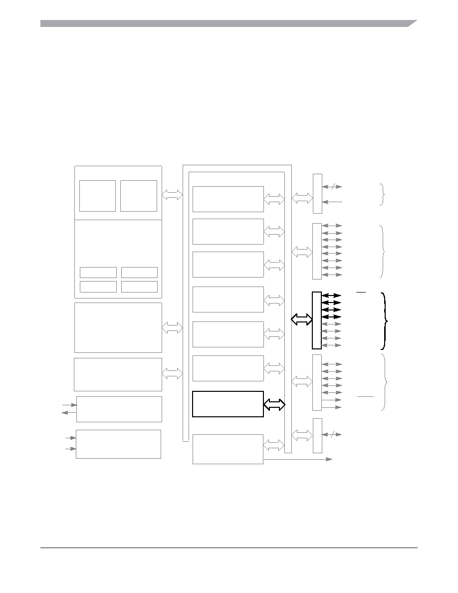
Chapter 13
Serial Peripheral Interface (S08SPIV3)
The SPI is only available on the MC9S08RGxx versions of this family of microcontrollers. The SPI pins
are shared with PTC4-PTC7 port pins. When the SPI is enabled these pins are controlled by the SPI
module.
Figure 13-1. MC9S08RC/RD/RE/RG Block Diagram Highlighting SPI Block and Pins
PTD3
PTD4/ACMP1–
PTD5/ACMP1+
PTD6/TPM1CH0
PTC1/KBI2P1
PTC0/KBI2P0
VSS
VDD
PTB3
PTB2
PTA7/KBI1P7–
PTB0/TxD1
PTB1/RxD1
PTD2/IRQ
PTD1/RESET
PTD0/BKGD/MS
PTC7/SS1
PTC6/SPSCK1
PTC5/MISO1
PTC4/MOSI1
PTC3/KBI2P3
PTC2/KBI2P2
POR
T
A
POR
T
C
POR
T
D
POR
T
B
8-BIT KEYBOARD
INTERRUPT MODULE (KBI1)
SERIAL PERIPHERAL
INTERFACE MODULE (SPI1)
USER FLASH
USER RAM
(RC/RD/RE/RG32/60 = 2048 BYTES)
DEBUG
MODULE (DBG)
(RC/RD/RE/RG60 = 63,364 BYTES)
HCS08 CORE
NOTES
NOTES 1, 5
2-CHANNEL TIMER/PWM
MODULE (TPM1)
PTE7–
POR
T
E
PTB5
PTB4
PTE6
PTB7/TPM1CH1
MODULE (ACMP1)
HCS08 SYSTEM CONTROL
RESETS AND INTERRUPTS
MODES OF OPERATION
POWER MANAGEMENT
VOLTAGE
REGULATOR
RTI
ANALOG COMPARATOR
COP
IRQ
LVD
INTERNAL BUS
LOW-POWER OSCILLATOR
INTERFACE MODULE (SCI1)
SERIAL COMMUNICATIONS
7
PTA1/KBI1P1
8
PTE0
NOTE 1
NOTES1, 2
NOTE 1
(RC/RD/RE/RG32 = 32,768 BYTES)
(RC/RD/RE8/16 = 1024 BYTES)
(RC/RD/RE16 = 16,384 BYTES)
XTAL
EXTAL
CARRIER MODULATOR
TIMER MODULE (CMT)
1, 3, 4
4-BIT KEYBOARD
INTERRUPT MODULE (KBI2)
IRO NOTE 5
PTA0/KBI1P0
(RC/RD/RE8 = 8192 BYTES)
BDC
CPU
NOTES:
1. Port pins are software configurable with pullup device if input port
2. PTA0 does not have a clamp diode to VDD. PTA0 should not be driven above VDD. Also, PTA0 does not pullup to VDD when internal
pullup is enabled.
3. IRQ pin contains software congurable pullup/pulldown device if IRQ enabled (IRQPE = 1)
4. The RESET pin contains integrated pullup device enabled if reset enabled (RSTPE = 1)
5. High current drive
6. Pins PTA[7:4] contain both pullup and pulldown devices. Pulldown enabled when KBI is enabled (KBIPEn = 1) and rising edge is
selected (KBEDGn = 1).
相關PDF資料 |
PDF描述 |
|---|---|
| MC9S08RD32CPE | 8-BIT, FLASH, 8 MHz, MICROCONTROLLER, PDIP28 |
| MC9S08RD60CPE | 8-BIT, FLASH, 8 MHz, MICROCONTROLLER, PDIP28 |
| MC9S08RE8FGE | 8-BIT, FLASH, 8 MHz, MICROCONTROLLER, PQFP44 |
| MC9S08RE32CFGE | 8-BIT, FLASH, 8 MHz, MICROCONTROLLER, PQFP44 |
| MC9S08RG60CFGE | 8-BIT, FLASH, 8 MHz, MICROCONTROLLER, PQFP44 |
相關代理商/技術參數(shù) |
參數(shù)描述 |
|---|---|
| MC9S08RE32DWE | 制造商:FREESCALE 制造商全稱:Freescale Semiconductor, Inc 功能描述:Microcontrollers |
| MC9S08RE32FDE | 制造商:FREESCALE 制造商全稱:Freescale Semiconductor, Inc 功能描述:Microcontrollers |
| MC9S08RE32FG | 制造商:MOTOROLA 制造商全稱:Motorola, Inc 功能描述:Microcontrollers |
| MC9S08RE32FGE | 制造商:FREESCALE 制造商全稱:Freescale Semiconductor, Inc 功能描述:Microcontrollers |
| MC9S08RE32FJ | 制造商:MOTOROLA 制造商全稱:Motorola, Inc 功能描述:Microcontrollers |
發(fā)布緊急采購,3分鐘左右您將得到回復。