- 您現(xiàn)在的位置:買賣IC網(wǎng) > PDF目錄382305 > MC33888 (Motorola, Inc.) Quad High-Side and Octal Low-Side Switch for Automotive PDF資料下載
參數(shù)資料
| 型號: | MC33888 |
| 廠商: | Motorola, Inc. |
| 英文描述: | Quad High-Side and Octal Low-Side Switch for Automotive |
| 中文描述: | 四高邊和八路低端汽車開關(guān) |
| 文件頁數(shù): | 17/32頁 |
| 文件大?。?/td> | 667K |
| 代理商: | MC33888 |
第1頁第2頁第3頁第4頁第5頁第6頁第7頁第8頁第9頁第10頁第11頁第12頁第13頁第14頁第15頁第16頁當前第17頁第18頁第19頁第20頁第21頁第22頁第23頁第24頁第25頁第26頁第27頁第28頁第29頁第30頁第31頁第32頁

MOTOROLA ANALOG INTEGRATED CIRCUIT DEVICE DATA
33888
17
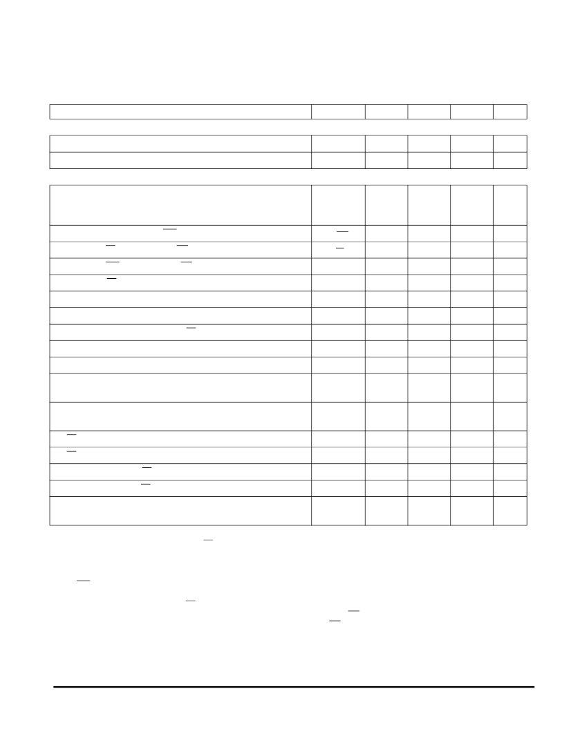
POWER OUTPUT TIMING (continued)
Peak Current Limit Timer
(Note 36)
t
PCT
40
70
100
ms
Direct Input Switching Frequency
(Note 37)
f
PWM
–
125
–
Hz
SPI INTERFACE TIMING
(Note 38)
Recommended Frequency of SPI Operation
Normal Mode
Extended Mode: V
DD
= 3.4 V; V
PWR
= 4.5 V, APNB Suffix Only
f
SPI
–
–
–
–
3.0
2.1
MHz
Required Low State Duration for
RST
(Note 39)
t
WRST
–
50
167
ns
Rising Edge of
CS
to Falling Edge of
CS
(Required Setup Time)
(Note 40)
t
CS
–
–
300
ns
Rising Edge of
RST
to Falling Edge of
CS
(Required Setup Time)
(Note 40)
t
ENBL
–
–
5.0
μ
s
Falling Edge of
CS
to Rising Edge of SCLK (Required Setup Time)
(Note 40)
t
LEAD
–
50
167
ns
Required High State Duration of SCLK (Required Setup Time)
(Note 40)
t
WSCLKh
–
–
167
ns
Required Low State Duration of SCLK (Required Setup Time)
(Note 40)
t
WSCLKl
–
–
167
ns
Falling Edge of SCLK to Rising Edge of
CS
(Required Setup Time)
(Note 40)
t
LAG
–
50
167
ns
SI to Falling Edge of SCLK (Required Setup Time)
(Note 40)
t
SI(SU)
–
25
83
ns
Falling Edge of SCLK to SI (Required Hold Time)
(Note 40)
t
SI(HOLD)
–
25
83
ns
SO Rise Time
C
L
= 200 pF
t
RSO
–
25
50
ns
SO Fall Time
C
L
= 200 pF
t
FSO
–
25
50
ns
SI,
CS
, SCLK, Incoming Signal Rise Time
(Note 41)
t
RSI
–
–
50
ns
SI,
CS
, SCLK, Incoming Signal Fall Time
(Note 41)
t
FSI
–
–
50
ns
Time from Falling Edge of
CS
to SO Low Impedance
(Note 42)
t
SO(EN)
–
–
145
ns
Time from Rising Edge of
CS
to SO High Impedance
(Note 43)
t
SO(DIS)
–
65
145
ns
Time from Rising Edge of SCLK to SO Data Valid
(Note 44)
0.2 V
DD
≤
SO
≥
0.8 V
DD
, C
L
= 200 pF
t
VALID
–
65
105
ns
Notes
36.
37.
t
PCT
measured from the rising edge of
CS
to 90% of I
LIMPKHS[x,x]
when the peak current limit is enabled.
This frequency is a typical value. Maximum switching frequencies are dictated by the turn-ON delay, turn-OFF delay, output rise and fall
times, and the maximum allowable junction temperature.
Symmetrical 50% duty cycle SCLK clock period of 333 ns.
RST
low duration measured with outputs enabled and going to OFF or disabled condition.
Maximum setup time required for the 33888 is the minimum guaranteed time needed from the MCU.
Rise and fall time of incoming SI,
CS
, and SCLK signals suggested for design consideration to prevent the occurrence of double pulsing.
Time required for output status data to be available for use at SO. 1.0 k
pullup on
CS.
Time required for output status data to be terminated at SO. 1.0 k
pullup on
CS.
Time required to obtain valid data out from SO following the rise of SCLK.
38.
39.
40.
41.
42.
43.
44.
DYNAMIC ELECTRICAL CHARACTERISTICS (continued)
Characteristics noted under conditions 6.0 V
≤
V
PWR
≤
27 V, 4.5 V
≤
V
DD
≤
5.5 V, -40
°
C
≤
T
J
≤
150
°
C unless otherwise noted. Typical
values noted reflect the approximate parameter mean at T
A
= 25
°
C under nominal conditions unless otherwise noted.
Characteristic
Symbol
Min
Typ
Max
Unit
F
Freescale Semiconductor, Inc.
For More Information On This Product,
Go to: www.freescale.com
n
.
相關(guān)PDF資料 |
PDF描述 |
|---|---|
| MC33888FB | Quad High-Side and Octal Low-Side Switch for Automotive |
| MC33888FBR2 | Quad High-Side and Octal Low-Side Switch for Automotive |
| MC33972 | Multiple Switch Detection Interface with Suppressed Wake-Up |
| MC33972DWB | Multiple Switch Detection Interface with Suppressed Wake-Up |
| MC33972EW | Multiple Switch Detection Interface with Suppressed Wake-Up |
相關(guān)代理商/技術(shù)參數(shù) |
參數(shù)描述 |
|---|---|
| MC33888APNBR2 | 制造商:Freescale Semiconductor 功能描述: 制造商:FREESCALE-SEMI 功能描述: |
| MC33888FB | 功能描述:電源開關(guān) IC - 配電 QHSOLSS RoHS:否 制造商:Exar 輸出端數(shù)量:1 開啟電阻(最大值):85 mOhms 開啟時間(最大值):400 us 關(guān)閉時間(最大值):20 us 工作電源電壓:3.2 V to 6.5 V 電源電流(最大值): 最大工作溫度:+ 85 C 安裝風(fēng)格:SMD/SMT 封裝 / 箱體:SOT-23-5 |
| MC33888FBR2 | 功能描述:電源開關(guān) IC - 配電 QHSOLSS RoHS:否 制造商:Exar 輸出端數(shù)量:1 開啟電阻(最大值):85 mOhms 開啟時間(最大值):400 us 關(guān)閉時間(最大值):20 us 工作電源電壓:3.2 V to 6.5 V 電源電流(最大值): 最大工作溫度:+ 85 C 安裝風(fēng)格:SMD/SMT 封裝 / 箱體:SOT-23-5 |
| MC33888PNB | 制造商:FREESCALE-SEMI 功能描述: |
| MC33888PNBR2 | 制造商:FREESCALE-SEMI 功能描述: |
發(fā)布緊急采購,3分鐘左右您將得到回復(fù)。