- 您現(xiàn)在的位置:買賣IC網(wǎng) > PDF目錄382304 > MC33560DTBR2 (ON SEMICONDUCTOR) Power Management and Interface IC for Smartcard Readers and Couplers PDF資料下載
參數(shù)資料
| 型號(hào): | MC33560DTBR2 |
| 廠商: | ON SEMICONDUCTOR |
| 元件分類: | 模擬信號(hào)調(diào)理 |
| 英文描述: | Power Management and Interface IC for Smartcard Readers and Couplers |
| 中文描述: | SPECIALTY ANALOG CIRCUIT, PDSO24 |
| 封裝: | PLASTIC, TSSOP-24 |
| 文件頁(yè)數(shù): | 14/24頁(yè) |
| 文件大小: | 435K |
| 代理商: | MC33560DTBR2 |
第1頁(yè)第2頁(yè)第3頁(yè)第4頁(yè)第5頁(yè)第6頁(yè)第7頁(yè)第8頁(yè)第9頁(yè)第10頁(yè)第11頁(yè)第12頁(yè)第13頁(yè)當(dāng)前第14頁(yè)第15頁(yè)第16頁(yè)第17頁(yè)第18頁(yè)第19頁(yè)第20頁(yè)第21頁(yè)第22頁(yè)第23頁(yè)第24頁(yè)

MC33560
http://onsemi.com
14
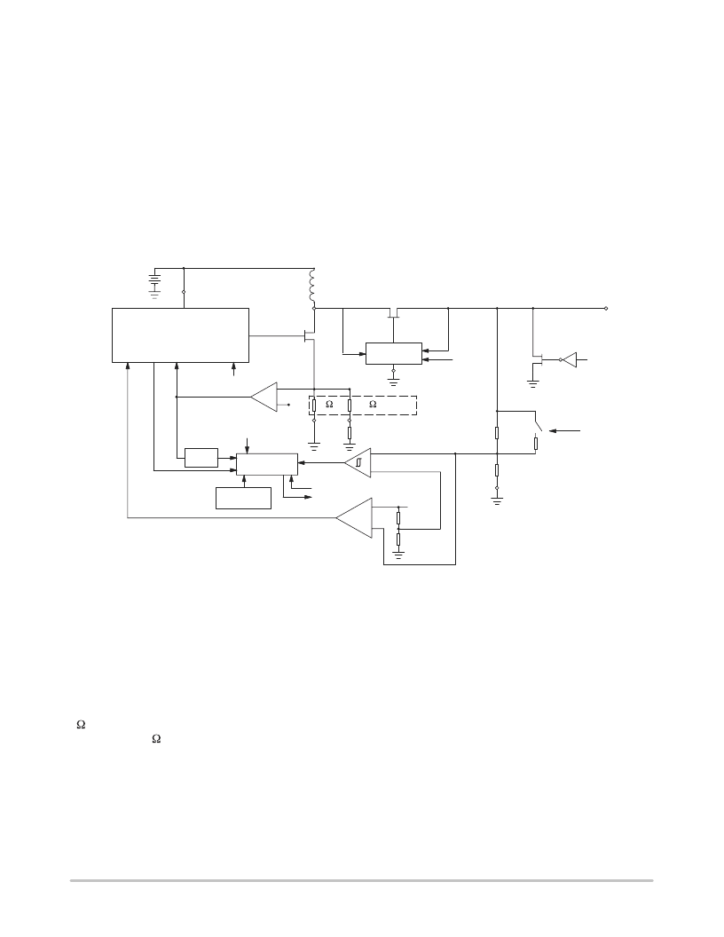
The MC33560 has a built in oscillator; the DC/DC
converter requires only one inductor and the output filtering
capacitor to operate.
Step–Up Operation:
When the card supply voltage is
lower than the battery voltage, the converter operates like a
boost converter; the active rectifier behavior is similar to
that of a diode.
Step–Down Operation:
When the card supply voltage is
higher than the battery voltage, the rectifier control circuit
puts the power rectifying transistor in conduction when the
L1 voltage reaches VBAT+VFSAT22. The voltage across the
rectifying transistor is higher than in step–up operation. The
efficiency is lower, and similar to a linear regulator.
Fault Detection:
The DC/DC converter has several
features that help to avoid electrical overstress of the
MC33560 and of the smartcard, and help to ensure that data
transmission with the smartcard occurs only when its supply
voltage is within predetermined limits. These functions are:
overtemperature detection,
current limitation, and
card supply undervoltage detection.
The level at which current will be limited is defined by the
maximum card supply current programmed with the
external components L1 and RLIM.
The undervoltage detection levels for 3V and 5V card
supply are preset internally to the MC33560.
Figure 22. DC/DC Converter Functional Block
PWN
Low Side
Switch
FEED
BACK CLOCK OFF
VBAT
ON /OFF
L1
STOP
ON /OFF
+
–
–
+
LAND
COUNTER
OVER TEMP
DETECTION
DIGITAL
FILTER
–
+
ON /OFF
RECTIFIER
CONTROL
120 mV
PGND
ILIM
RLIM(external)
Internal
resistors
2
0.5
ON /OFF
Rectifier Switch
CRDVCC
Active pull–down
switch
3V/5V
CRDGND
VREF
UNDER VOLTAGE
DETECTOR
EAMP.
VBATOK
CONVERTER
FAULT
CRDGND
ILIMCOMP
The overcurrent and undervoltage protection features are
complementary, and will shut the circuit off either if the
overcurrent is high enough to bring the CRDVCC output
below the preset threshold, either after 160ms (typ.)
In addition, the DC/DC converter will be allowed to start
only if the battery supply voltage is high enough to allow
normal operation (1.8V).
The undervoltage comparator has a hysteresis and a delay
of typically 20ms to ensure stable operation. The current
detector is a comparator associated with two resistors: one
2 attached to
PGND
and usually connected to analog
ground, and a 0.5 attached to
ILIM
, usually connected to
ground through an external resistor to adjust the maximum
peak current. The voltage developed across this resistor
network is then compared to a 120mV (typical) reference
voltage, and the comparator output performs a
cycle–by–cycle peak current limitation by switching off the
low side transistor when the voltage exceeds 120 mV.
The internal
ILIMCOMP
signal is monitored to stop the
converter if current limitation is continuously detected
during 160ms (typical). This allows normal operation with
high filtering capacitance and low peak current, even at
converter start–up. As a result, a short circuit to ground on
the card connector or a continuous overcurrent is reported by
RDYMOD
160ms (typical) after power up.
Unexpected card extraction
:
The MC33560 detects card
extraction and runs a power down sequence if card power is
still on when extraction occurs. An active pull–down switch
clamps CRDVCC to GND within 150
μ
s (max) after
extraction is detected. The external capacitors will then be
discharged. With typical capacitor values of 10
μ
F and 47nF
as indicated in the application schematic, the time needed to
discharge CRDVCC to a voltage below 0.4V can be
estimated to less than 750
μ
s. The total time aftercard
extraction detection until CRDVCC reaches 0.4V is then
estimated to 900
μ
s (max). All smartcard connector contacts
will be deactivated before CRDVCC deactivation. This
ensures that no electrical damage will be caused to the
smartcard under abnormal extraction conditions.
相關(guān)PDF資料 |
PDF描述 |
|---|---|
| MC33565 | Single Output LDO, 400mA, Fixed(3.0V), Low Noise, Fast Transient Response 5-SOT-23 -40 to 85 |
| MC33565D | Single Output LDO, 400mA, Fixed(3.0V), Low Noise, Fast Transient Response 5-SOT-23 -40 to 85 |
| MC33567D-1 | Dual Linear Controller for High Current Voltage Regulation |
| MC33567 | Dual Linear Controller for High Current Voltage Regulation(用于大電流穩(wěn)壓的雙線性控制器) |
| MC33567D-1R2 | Dual Linear Controller for High Current Voltage Regulation |
相關(guān)代理商/技術(shù)參數(shù) |
參數(shù)描述 |
|---|---|
| MC33560DTBR2G | 功能描述:輸入/輸出控制器接口集成電路 3V/5V Smartcard Power Management RoHS:否 制造商:Silicon Labs 產(chǎn)品: 輸入/輸出端數(shù)量: 工作電源電壓: 最大工作溫度:+ 85 C 最小工作溫度:- 40 C 安裝風(fēng)格:SMD/SMT 封裝 / 箱體:QFN-64 封裝:Tray |
| MC33560DW | 功能描述:輸入/輸出控制器接口集成電路 3V/5V Smartcard RoHS:否 制造商:Silicon Labs 產(chǎn)品: 輸入/輸出端數(shù)量: 工作電源電壓: 最大工作溫度:+ 85 C 最小工作溫度:- 40 C 安裝風(fēng)格:SMD/SMT 封裝 / 箱體:QFN-64 封裝:Tray |
| MC33560DWR2 | 功能描述:輸入/輸出控制器接口集成電路 3V/5V Smartcard RoHS:否 制造商:Silicon Labs 產(chǎn)品: 輸入/輸出端數(shù)量: 工作電源電壓: 最大工作溫度:+ 85 C 最小工作溫度:- 40 C 安裝風(fēng)格:SMD/SMT 封裝 / 箱體:QFN-64 封裝:Tray |
| MC33560DWR2G | 功能描述:輸入/輸出控制器接口集成電路 3V/5V Smartcard Power Management RoHS:否 制造商:Silicon Labs 產(chǎn)品: 輸入/輸出端數(shù)量: 工作電源電壓: 最大工作溫度:+ 85 C 最小工作溫度:- 40 C 安裝風(fēng)格:SMD/SMT 封裝 / 箱體:QFN-64 封裝:Tray |
| MC33565D | 功能描述:低壓差穩(wěn)壓器 - LDO 3.3V 200mA w/Sleep RoHS:否 制造商:Texas Instruments 最大輸入電壓:36 V 輸出電壓:1.4 V to 20.5 V 回動(dòng)電壓(最大值):307 mV 輸出電流:1 A 負(fù)載調(diào)節(jié):0.3 % 輸出端數(shù)量: 輸出類型:Fixed 最大工作溫度:+ 125 C 安裝風(fēng)格:SMD/SMT 封裝 / 箱體:VQFN-20 |
發(fā)布緊急采購(gòu),3分鐘左右您將得到回復(fù)。