- 您現(xiàn)在的位置:買賣IC網(wǎng) > PDF目錄385557 > MAX9993ETP-T (MAXIM INTEGRATED PRODUCTS INC) High-Linearity 1700MHz to 2200MHz Down- Conversion Mixer with LO Buffer/Switch PDF資料下載
參數(shù)資料
| 型號(hào): | MAX9993ETP-T |
| 廠商: | MAXIM INTEGRATED PRODUCTS INC |
| 元件分類: | 衰減器 |
| 英文描述: | High-Linearity 1700MHz to 2200MHz Down- Conversion Mixer with LO Buffer/Switch |
| 中文描述: | 1700 MHz - 2200 MHz RF/MICROWAVE DOUBLE BALANCED MIXER, 28 dB CONVERSION LOSS-MAX |
| 封裝: | 5 X 5 MM, 0.80 MM HEIGHT, MO-220, QFN-20 |
| 文件頁(yè)數(shù): | 2/12頁(yè) |
| 文件大?。?/td> | 492K |
| 代理商: | MAX9993ETP-T |
M
High-Linearity 1700MHz to 2200MHz Down-
Conversion Mixer with LO Buffer/Switch
2
_______________________________________________________________________________________
ABSOLUTE MAXIMUM RATINGS
V
CC
..........................................................................-0.3V to 5.5V
RF (RF is DC shorted to GND through balun).....................50mA
LO1, LO2 to GND ...............................................................±0.3V
TAP, IF+, IF- to GND ..................................-0.3V to (V
CC
+ 0.3V)
LOSEL to GND................................-0.3V to (V
CC
(pin 8) + 0.3V)
LOBIAS, IFBIAS, LEXT to GND ..................-0.3V to (V
CC
+ 0.3V)
RF and LO Input Power..................................................+22dBm
Stresses beyond those listed under “Absolute Maximum Ratings” may cause permanent damage to the device. These are stress ratings only, and functional
operation of the device at these or any other conditions beyond those indicated in the operational sections of the specifications is not implied. Exposure to
absolute maximum rating conditions for extended periods may affect device reliability.
Continuous Power Dissipation (T
A
= +70
°
C)
20-Lead Thin QFN
(derate 30.3mW/
°
C above T
A
= +70
°
C) ....................2200mW
θ
JA
....................................................................................33
°
C/W
Operating Temperature Range ...........................-40
°
C to +85
°
C
Storage Temperature Range.............................-65
°
C to +150
°
C
Lead Temperature (soldering, 10s).................................+300
°
C
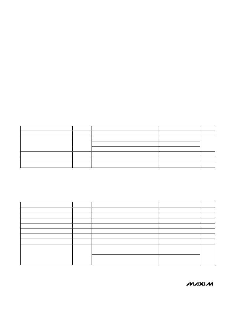
DC ELECTRICAL CHARACTERISTICS
(
Typical Operating Circuit
as shown, no input RF or LO signals applied. V
CC
= 4.75V to 5.25V, T
A
= -40
°
C to +85
°
C. Typical values are
at V
CC
= 5.0V and T
A
= +25
°
C, unless otherwise noted.)
PARAMETER
SYMBOL
CONDITIONS
Supply Voltage
V
CC
Total supply current
V
CC
(pin 8)
Supply Current
I
CC
IF+/IF- (total of both)
LOSEL Input High Voltage
V
IH
LOSEL Input Low Voltage
V
IL
LOSEL Input Current
I
IL
and I
IH
MIN
4.75
TYP
5.00
202
87
103
MAX
5.25
230
105
133
UNITS
V
mA
2.0
V
V
μA
0.8
+5
-5
AC ELECTRICAL CHARACTERISTICS
(
Typical Operating Circuit
, 4.75V < V
CC
< 5.75V, -40
°
C < T
A
< +85
°
, RF and LO ports are driven from 50
sources, 0dBm < P
LO
<
+6dBm, P
RF
= -5dBm, 1700MHz < f
RF
< 2200MHz, 1400MHz < f
LO
< 2000MHz, f
IF
= 200MHz. Typical values are for T
A
= +25
°
C
V
CC
= 5.0V, P
LO
= +3dBm, f
RF
= 1900MHz, f
LO
= 1700MHz, 200MHz IF.) (Notes 1, 2)
PARAMETER
SYMBOL
f
RF
f
LO
f
IF
G
C
CONDITIONS
MIN
1700
1400
50
TYP
MAX
2200
2000
350
UNITS
MHz
MHz
MHz
dB
dB/
°
C
dB
dBm
RF Frequency
LO Frequency
IF Frequency
Conversion Gain
Gain Variation Over Temperature
Gain Variation from Nominal (3
σ
)
Input Compression Point
(Note 6)
(Note 3)
T
A
= -40
°
C to +85
°
C
8.5
0.0012
0.45
12.6
P
1dB
Two RF tones: -5dBm each at 1950MHz
and 1951MHz, LO: +3dBm at 1750MHz
24
Input Third-Order Intercept Point
(Note 3)
IIP3
Two RF tones: -5dBm each at 2200MHz
and 2201MHz, LO: +3dBm at 2000MHz
23
dBm
相關(guān)PDF資料 |
PDF描述 |
|---|---|
| MB200 | RECTIFIERS |
| MB201 | RECTIFIERS |
| MB202 | RECTIFIERS |
| MB204 | RECTIFIERS |
| MB206 | RECTIFIERS |
相關(guān)代理商/技術(shù)參數(shù) |
參數(shù)描述 |
|---|---|
| MAX9993ETP-TG069 | 制造商:Rochester Electronics LLC 功能描述: 制造商:Maxim Integrated Products 功能描述: |
| MAX9993EVKIT | 功能描述:射頻開發(fā)工具 RoHS:否 制造商:Taiyo Yuden 產(chǎn)品:Wireless Modules 類型:Wireless Audio 工具用于評(píng)估:WYSAAVDX7 頻率: 工作電源電壓:3.4 V to 5.5 V |
| MAX9994ETP | 功能描述:上下轉(zhuǎn)換器 SiGe 1700-2200MHz Downconversion Mixer RoHS:否 制造商:Texas Instruments 產(chǎn)品:Down Converters 射頻:52 MHz to 78 MHz 中頻:300 MHz LO頻率: 功率增益: P1dB: 工作電源電壓:1.8 V, 3.3 V 工作電源電流:120 mA 最大功率耗散:1 W 最大工作溫度:+ 85 C 安裝風(fēng)格:SMD/SMT 封裝 / 箱體:PQFP-128 |
| MAX9994ETP+ | 功能描述:上下轉(zhuǎn)換器 SiGe 1700-2200MHz Downconversion Mixer RoHS:否 制造商:Texas Instruments 產(chǎn)品:Down Converters 射頻:52 MHz to 78 MHz 中頻:300 MHz LO頻率: 功率增益: P1dB: 工作電源電壓:1.8 V, 3.3 V 工作電源電流:120 mA 最大功率耗散:1 W 最大工作溫度:+ 85 C 安裝風(fēng)格:SMD/SMT 封裝 / 箱體:PQFP-128 |
| MAX9994ETP+D | 制造商:Maxim Integrated Products 功能描述:UP/DOWN CONV MIXER 5V 2.2GHZ 20TQFN EP - Rail/Tube |
發(fā)布緊急采購(gòu),3分鐘左右您將得到回復(fù)。