- 您現(xiàn)在的位置:買(mǎi)賣(mài)IC網(wǎng) > PDF目錄1946 > MAX9273GTL/V+ (Maxim Integrated Products)IC SERIALIZER 22BIT GMSL 40TQFN PDF資料下載
參數(shù)資料
| 型號(hào): | MAX9273GTL/V+ |
| 廠商: | Maxim Integrated Products |
| 文件頁(yè)數(shù): | 28/49頁(yè) |
| 文件大小: | 0K |
| 描述: | IC SERIALIZER 22BIT GMSL 40TQFN |
| 標(biāo)準(zhǔn)包裝: | 50 |
| 系列: | * |
第1頁(yè)第2頁(yè)第3頁(yè)第4頁(yè)第5頁(yè)第6頁(yè)第7頁(yè)第8頁(yè)第9頁(yè)第10頁(yè)第11頁(yè)第12頁(yè)第13頁(yè)第14頁(yè)第15頁(yè)第16頁(yè)第17頁(yè)第18頁(yè)第19頁(yè)第20頁(yè)第21頁(yè)第22頁(yè)第23頁(yè)第24頁(yè)第25頁(yè)第26頁(yè)第27頁(yè)當(dāng)前第28頁(yè)第29頁(yè)第30頁(yè)第31頁(yè)第32頁(yè)第33頁(yè)第34頁(yè)第35頁(yè)第36頁(yè)第37頁(yè)第38頁(yè)第39頁(yè)第40頁(yè)第41頁(yè)第42頁(yè)第43頁(yè)第44頁(yè)第45頁(yè)第46頁(yè)第47頁(yè)第48頁(yè)第49頁(yè)
MAX9273
22-Bit GMSL Serializer with Coax or
STP Cable Drive
34
Maxim Integrated
serializer and deserializer have unequal DBL settings
and HVEN = 0, then HS/VS inversion should only be used
on the side that has DBL = 1. HS/VS encoding sends
packets when HSYNC or VSYNC is low, use HS/VS inver-
sion register bits if the input HSYNC and VSYNC signals
use an active-low convention to send data packets dur-
ing the inactive pixel clock periods.
Serial Output
The driver output is programmable for two types of cable:
100I twisted pair and 50I coax (contact the factory for
serializers with 75I cable drive).
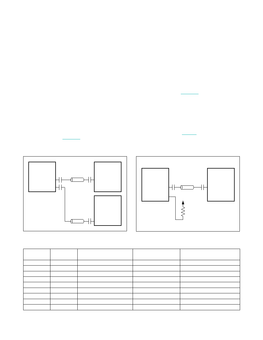
Coax-Mode Splitter
In coax mode, OUT+ and OUT- are active. This enables
use as a 1:2 splitter (Figure 31). In coax mode, connect
OUT+ to IN+ of the deserializer. Connect OUT- to IN- of
the second deserializer. Control-channel data is broad-
cast from the serializer to both deserializers and their
attached peripherals. Assign a unique device address to
send control data to one deserializer. Leave all unused
IN_ pins unconnected, or connect them to ground
through 50I and a capacitor for increased power-supply
rejection. If OUT- is not used, connect OUT- to AVDD
through a 50I resistor (Figure 32). When there are FCs
at the serializer, and at each deserializer, only one FC
can communicate at a time. Disable one splitter control-
channel link to prevent contention. Use the DIS_REV_P or
DIS_REV_N register bits to disable a control-channel link.
Configuration Inputs (CONF1, CONF0)
CONF1 and CONF0 determine the power-up values of the
serial output type, the input data latch, and the control-
channel interface type (Table 9). These functions can
be changed after power-up by writing to the appropriate
register bits
Figure 31. 2:1 Coax-Mode Splitter Connection Diagram
Figure 32. Coax-Mode Connection Diagram
Table 9. Configuration Input Map
CONF1
CONF0
CxTP
(OUT+/OUT- OUTPUT TYPE)
ES
(PCLKIN LATCH EDGE)
I2CSEL
(CONTROL-CHANNEL TYPE)
Low
1 (coax)
1 (falling)
1 (I2C-to-I2C)
Low
Mid
1 (coax)
1 (falling)
0 (UART-to-I2C/UART)
Low
High
1 (coax)
0 (rising)
1 (I2C-to-I2C)
Mid
Low
1 (coax)
0 (rising)
0 (UART-to-I2C/UART)
Mid
0 (STP)
1 (falling)
1 (I2C-to-I2C)
Mid
High
0 (STP)
1 (falling)
0 (UART-to-I2C/UART)
High
Low
0 (STP)
0 (rising)
1 (I2C-to-I2C)
High
Mid
0 (STP)
0 (rising)
0 (UART-to-I2C/UART)
High
Do not use
OUT+
OUT-
IN+
IN-
IN+
IN-
GMSL
DESERIALIZER
GMSL
DESERIALIZER
MAX9273
OUT+
OUT-
IN+
IN-
AVDD
50I
GMSL
DESERIALIZER
MAX9273
相關(guān)PDF資料 |
PDF描述 |
|---|---|
| MAX9390EHJ+ | IC CROSSPOINT SWITCH DUAL 32TQFP |
| MAX9392EHJ+ | IC CROSSPOINT SWITCH DUAL 32TQFP |
| MAX9402EHJ+ | IC BUFF/RCVR DIFF QUAD 32TQFP |
| MAX9595CTM+T | IC AUDIO/VIDEO SWIT DUAL 48TQFN |
| MAX9598CTL+T | IC SWITCH DUAL SCART 40TQFN |
相關(guān)代理商/技術(shù)參數(shù) |
參數(shù)描述 |
|---|---|
| MAX9275GTN/V+T | 制造商:Maxim Integrated Products 功能描述:SERIALIZER WITH PARALLEL CMOS INPUTS, NON-HDCP - Tape and Reel |
| MAX9276GTN/V+GG6 | 制造商:Maxim Integrated Products 功能描述:IC DESERIALIZER GMSL 3.12GBPS |
| MAX9276GTN/V+T | 制造商:Maxim Integrated Products 功能描述:3.12GBPS GMSL DESERIALIZERS FOR COAX OR STP INPUTS AND PARAL - Tape and Reel |
| MAX9276GTN+ | 制造商:Maxim Integrated Products 功能描述:DE-SERIALIZER WITH PARALLEL CMOS OUTPUTS, NON-HDCP - Rail/Tube |
| MAX9277GTM/V+GG7 | 制造商:Maxim Integrated Products 功能描述:IC SERIALIZER LVDS |
發(fā)布緊急采購(gòu),3分鐘左右您將得到回復(fù)。