- 您現(xiàn)在的位置:買賣IC網(wǎng) > PDF目錄385547 > MAX7000A (Altera Corporation) Programmable Logic Device PDF資料下載
參數(shù)資料
| 型號: | MAX7000A |
| 廠商: | Altera Corporation |
| 英文描述: | Programmable Logic Device |
| 中文描述: | 可編程邏輯器件 |
| 文件頁數(shù): | 50/60頁 |
| 文件大?。?/td> | 943K |
| 代理商: | MAX7000A |
第1頁第2頁第3頁第4頁第5頁第6頁第7頁第8頁第9頁第10頁第11頁第12頁第13頁第14頁第15頁第16頁第17頁第18頁第19頁第20頁第21頁第22頁第23頁第24頁第25頁第26頁第27頁第28頁第29頁第30頁第31頁第32頁第33頁第34頁第35頁第36頁第37頁第38頁第39頁第40頁第41頁第42頁第43頁第44頁第45頁第46頁第47頁第48頁第49頁當前第50頁第51頁第52頁第53頁第54頁第55頁第56頁第57頁第58頁第59頁第60頁
50
Altera Corporation
MAX 7000A Programmable Logic Device Data Sheet
Notes to tables:
(1)
These values are specified under the recommended operating conditions shown in
Table 11 on page 24
. See
Figure 12
for more information on switching waveforms.
(2)
These values are specified for a PIA fan-out of one LAB (16 macrocells). For each additional LAB fan-out in these
devices, add an additional 0.1 ns to the PIA timing value.
(3)
This minimum pulse width for preset and clear applies for both global clear and array controls. The
t
LPA
parameter
must be added to this minimum width if the clear or reset signal incorporates the
t
LAD
parameter into the signal
path.
(4)
This parameter is measured with a 16-bit loadable, enabled, up/down counter programmed into each LAB.
(5)
Operating conditions: V
CCIO
= 2.5
±
0.2 V for commercial and industrial use.
(6)
The
t
LPA
parameter must be added to the
t
LAD
,
t
LAC
,
t
IC
,
t
EN
,
t
SEXP
,
t
ACL
, and
t
CPPW
parameters for macrocells
running in low-power mode.
Power
Consumption
Supply power (P) versus frequency (
f
MAX
, in MHz) for MAX 7000A
devices is calculated with the following equation:
P = P
INT
+ P
IO
= I
CCINT
×
V
CC
+ P
IO
The P
IO
value, which depends on the device output load characteristics
and switching frequency, can be calculated using the guidelines given in
Application Note 74 (Evaluating Power for Altera Devices)
.
The I
CCINT
value depends on the switching frequency and the application
logic. The I
CCINT
value is calculated with the following equation:
I
CCINT
=
(A
×
MC
TON
) + [B
×
(MC
DEV
– MC
TON
)] + (C
×
MC
USED
×
f
MAX
×
tog
LC
)
t
RD
t
COMB
t
IC
t
EN
t
GLOB
t
PRE
t
CLR
t
PIA
t
LPA
Register delay
Combinatorial delay
Array clock delay
Register enable time
Global control delay
Register preset time
Register clear time
PIA delay
Low-power adder
1.6
1.6
2.7
2.5
1.1
2.3
2.3
1.3
11.0
2.0
2.0
3.4
3.1
1.4
2.9
2.9
1.6
10.0
2.7
2.7
4.5
4.2
1.8
3.8
3.8
2.1
10.0
3.2
3.2
5.4
5.0
2.2
4.6
4.6
2.6
10.0
ns
ns
ns
ns
ns
ns
ns
ns
ns
(2)
(6)
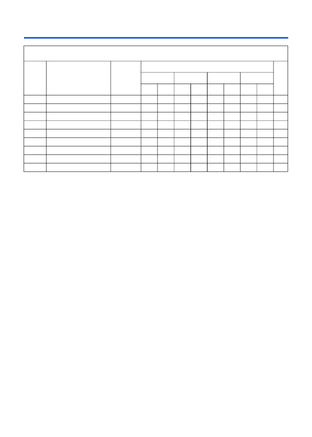
Table 27. EPM7256A Internal Timing Parameters (Part 2 of 2)
Note (1)
Symbol
Parameter
Conditions
Speed Grade
Unit
-6
-7
-10
-12
Min
Max
Min
Max
Min
Max
Min
Max
相關PDF資料 |
PDF描述 |
|---|---|
| MAX7000AE | Programmable Logic Device |
| MAX7000B | Programmable Logic Device |
| MAX7000 | Programmable Logic Device Family |
| MAX7000S | Programmable Logic Device Family |
| MAX7030 | RES 22.1-OHM 1% 0.1W 100PPM THICK-FILM SMD-0603 5K/REEL-7IN-PA |
相關代理商/技術參數(shù) |
參數(shù)描述 |
|---|---|
| MAX-7000A | 制造商:ALTERA 制造商全稱:Altera Corporation 功能描述:Programmable Logic Device |
| MAX7000AE | 制造商:ALTERA 制造商全稱:Altera Corporation 功能描述:Programmable Logic Device |
| MAX7000B | 制造商:ALTERA 制造商全稱:Altera Corporation 功能描述:Programmable Logic Device |
| MAX7000S | 制造商:ALTERA 制造商全稱:Altera Corporation 功能描述:Programmable Logic Device Family |
| MAX700C/D | 功能描述:監(jiān)控電路 RoHS:否 制造商:STMicroelectronics 監(jiān)測電壓數(shù): 監(jiān)測電壓: 欠電壓閾值: 過電壓閾值: 輸出類型:Active Low, Open Drain 人工復位:Resettable 監(jiān)視器:No Watchdog 電池備用開關:No Backup 上電復位延遲(典型值):10 s 電源電壓-最大:5.5 V 最大工作溫度:+ 85 C 安裝風格:SMD/SMT 封裝 / 箱體:UDFN-6 封裝:Reel |
發(fā)布緊急采購,3分鐘左右您將得到回復。